
1. Introduction
This manual provides essential information for the safe and effective installation, operation, and maintenance of your OELFFOW Miniature Smart WiFi Circuit Breaker, Model LBT-073-1. This device integrates multiple functionalities including a timer switch, power monitor, electric meter, and reconnector, offering comprehensive protection against leakage, over-current, and over/under voltage.
2. Safety Information
WARNING: Electrical installation and maintenance should only be performed by qualified personnel. Failure to follow these instructions may result in electric shock, fire, or serious injury.
- Always disconnect power at the main circuit breaker before installing or servicing the device.
- Ensure the device is installed in a dry environment, away from moisture and direct sunlight.
- Verify that the voltage and current ratings of your electrical system are compatible with the device specifications.
- This product cannot be used directly as the main circuit breaker. Connect a separate circuit breaker in front of this device to control the main power supply.
- Use appropriate personal protective equipment (PPE) during installation.
- Do not attempt to repair or modify the device. Contact qualified service personnel for assistance.
3. Package Contents
- 1 x OELFFOW Smart WiFi Miniature Circuit Breaker (Model LBT-073-1)
- 1 x User Manual (this document)
4. Product Features
The OELFFOW Smart WiFi Circuit Breaker offers advanced functionalities for electrical system management and protection:
- Multifunctionality: Acts as a timer switch, power monitor, electric meter, and reconnector.
- Comprehensive Protection: Includes leakage protection, over-current protection, and over/under voltage protection.
- Remote Control: Manage the device from anywhere using a mobile application, even without local Wi-Fi if a phone signal is available.
- Real-time Monitoring: View power utilization, voltage, current, and leakage values synchronously on your mobile phone.
- Remote Parameter Setting: Adjust overcurrent, overvoltage, undervoltage, and leakage current settings via the mobile app.
- Scheduled Operations: Set multiple timing schedules for automatic device operation.
- Durable Construction: Made from flame-retardant PC material for enhanced safety.
- DIN Rail Mounting: Designed for secure and easy installation on a DIN rail.
- Built-in Latching Relay: Prevents voltage instability and internal burning.
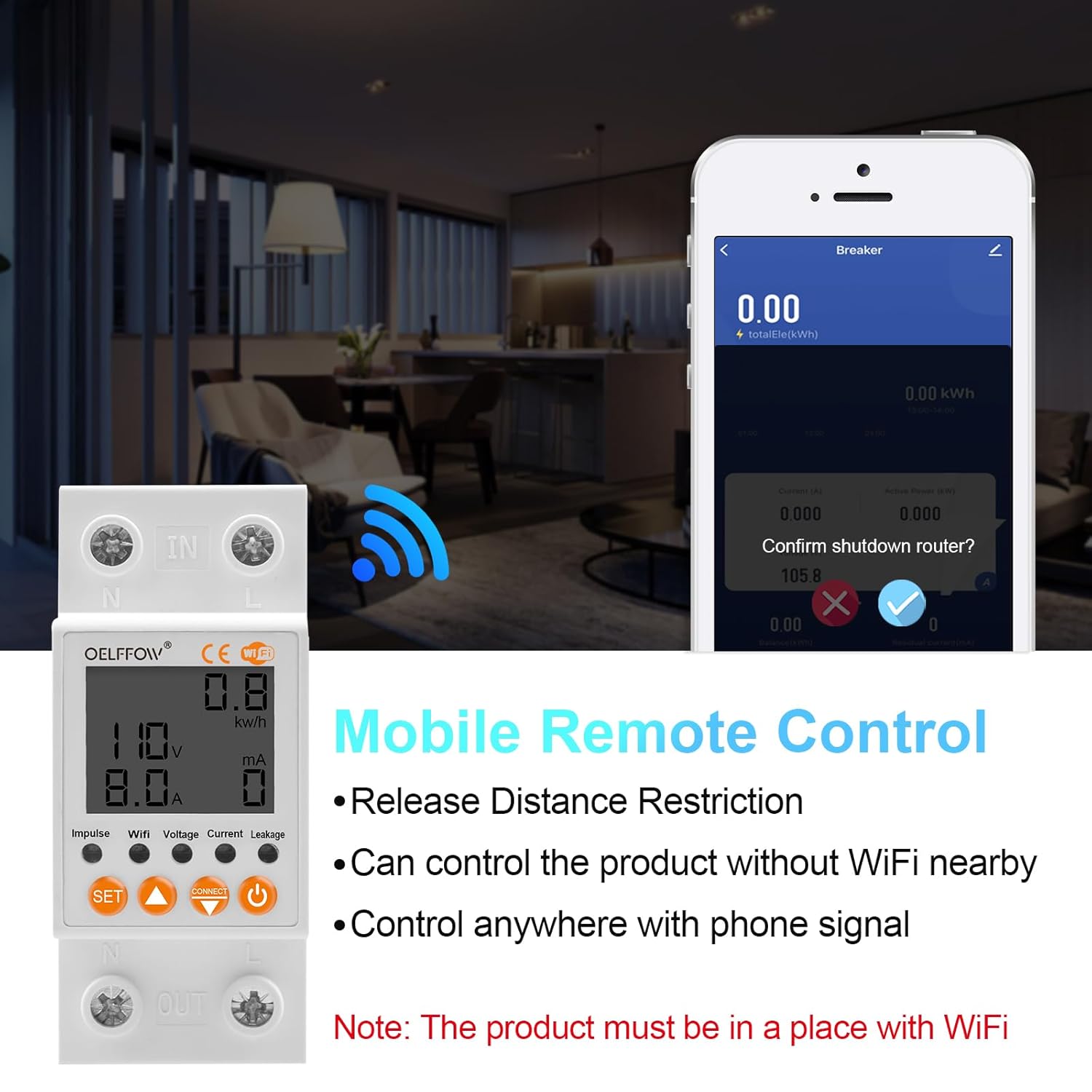
Figure 4.1: Overview of the circuit breaker's multifunctionality, including self-compound overvoltage and undervoltage protection, timing switch, electricity leakage breaker, reclosure, current limiter, and electricity meter.
5. Installation
5.1 Physical Installation
The device is designed for DIN rail mounting. Ensure the DIN rail is securely fixed before installation.
- Mount the circuit breaker onto a standard DIN rail. The device should click into place securely.
- Refer to the wiring diagram below for correct electrical connections. The device supports a top-in, bottom-out wiring configuration.
- Connect the Live wire to the 'IN' terminal marked 'L' and the Neutral wire to the 'IN' terminal marked 'N' at the top.
- Connect the load's Live wire to the 'OUT' terminal marked 'L' and the load's Neutral wire to the 'OUT' terminal marked 'N' at the bottom.
- Important: This product requires a separate circuit breaker installed upstream to control the main power supply. Do not use this device as the primary main circuit breaker.

Figure 5.1: Wiring diagram illustrating the connection of Live (red) and Neutral (blue) wires for top-in, bottom-out configuration. A caution note advises against using it as a main circuit breaker.
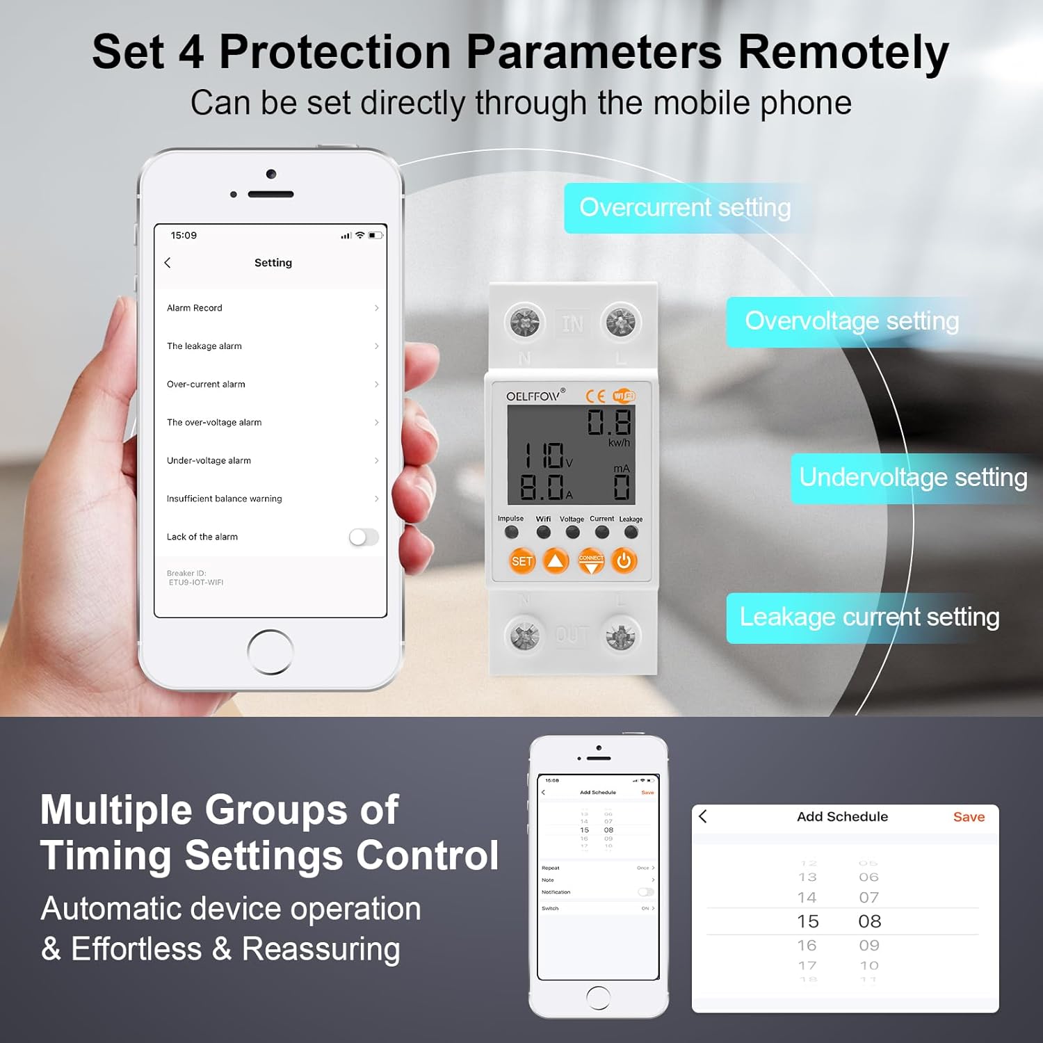
Figure 5.2: Details on the device's construction and installation features, including flame retardant material, secure DIN rail mounting, easy wiring access, and the built-in latching relay for stability.
5.2 App Installation and Device Pairing
To utilize the smart features, download the compatible mobile application (e.g., Smart Life or Tuya Smart) from your device's app store. Follow the in-app instructions to pair the circuit breaker with your smartphone.
- Ensure your smartphone is connected to a 2.4 GHz Wi-Fi network during the pairing process.
- Power on the circuit breaker after physical installation.
- Open the app and select "Add Device" or similar option.
- Follow the on-screen prompts to connect the device to your Wi-Fi network. This typically involves putting the device into pairing mode (often by pressing and holding the "CONNECT" button until the Wi-Fi indicator blinks).
- Once successfully paired, the device will appear in your app, ready for remote control and monitoring.
6. Operating Instructions
6.1 Remote Control via Mobile App
After successful pairing, you can control the circuit breaker remotely using the mobile application.
- On/Off Control: Toggle the circuit breaker's power state directly from the app interface.
- Distance Restriction Release: Control the product even without a local Wi-Fi connection, provided your phone has a signal.

Figure 6.1: Illustration of mobile remote control capabilities, allowing users to manage the circuit breaker via a smartphone app from any location with phone signal.
6.2 Real-time Monitoring
The mobile app displays real-time electrical data from the circuit breaker.
- Power Utilization: Displays energy consumption in kWh.
- Voltage Display: Shows the current line voltage in Volts (V).
- Current Display: Indicates the current load in Amperes (A).
- Leakage Value: Shows any detected leakage current in milliamperes (mA).
- Expense Management: The app may offer features for managing metering fees and recharging, if applicable.

Figure 6.2: The mobile application interface showing synchronous display of power utilization, voltage, current, and leakage values, along with options for remote management of metering fees.
6.3 Setting Protection Parameters
You can configure various protection thresholds directly through the mobile application to safeguard your electrical system.
- Overcurrent Setting: Define the maximum allowable current. If exceeded, the breaker will trip.
- Overvoltage Setting: Set the upper voltage limit. The breaker will trip if voltage goes above this.
- Undervoltage Setting: Set the lower voltage limit. The breaker will trip if voltage drops below this.
- Leakage Current Setting: Configure the maximum permissible leakage current. Exceeding this will cause the breaker to trip.

Figure 6.3: The mobile app's settings interface, allowing users to remotely configure protection parameters for overcurrent, overvoltage, undervoltage, and leakage current.
6.4 Scheduling and Timing Control
The app allows you to create schedules for automatic operation of the circuit breaker.
- Access the "Schedule" or "Timing" section within the app.
- Add new schedules by specifying desired on/off times and days of the week.
- This feature enables automated control, enhancing convenience and energy management.
7. Maintenance
- Keep the device clean and free from dust. Use a dry, soft cloth for cleaning.
- Do not use liquid cleaners or solvents.
- Regularly check all wiring connections to ensure they are secure.
- Periodically test the leakage protection function if a test button is present (refer to device markings).
- Ensure the device is not exposed to extreme temperatures or humidity.
8. Troubleshooting
| Problem | Possible Cause | Solution |
|---|---|---|
| Device does not power on. | No power supply; incorrect wiring; upstream breaker tripped. | Check main power supply. Verify wiring according to diagram. Reset upstream circuit breaker. |
| Cannot connect to Wi-Fi / App. | Incorrect Wi-Fi band (not 2.4 GHz); weak Wi-Fi signal; incorrect pairing procedure. | Ensure router is broadcasting 2.4 GHz Wi-Fi. Move device closer to router. Re-attempt pairing following app instructions, ensuring device is in pairing mode. |
| Circuit breaker trips frequently. | Overcurrent, overvoltage, undervoltage, or leakage detected; protection parameters set too low. | Check connected load for faults. Review and adjust protection parameters in the app if they are too sensitive for your application. Consult an electrician if issues persist. |
| Remote control not responding. | No internet connection on phone or device; app malfunction. | Check phone's internet connection. Verify device's Wi-Fi status. Restart the app or device. |
9. Specifications
| Parameter | Value |
|---|---|
| Brand | OELFFOW |
| Model Number | LBT-073-1 |
| Current Rating | 63 Amps |
| Circuit Breaker Type | Standard |
| Mounting Type | DIN Rail Mount |
| Number of Poles | 2 |
| Operating Voltage Range | AC 85-300V |
| Included Components | Smart WiFi Miniature Circuit Breaker |
| Country of Origin | USA |
10. Warranty and Support
For warranty information and technical support, please refer to the documentation provided with your purchase or contact OELFFOW customer service. Keep your purchase receipt as proof of purchase.
Note: Specific warranty terms may vary by region and retailer.