1. Introduction
The Eujgoov DSO3D12 is a highly integrated and versatile 3-in-1 device, combining the functionalities of a digital oscilloscope, a high-precision multimeter, and a signal generator. Designed for electronics enthusiasts, engineers, and students, this compact instrument offers powerful measurement and analysis capabilities. Its intuitive interface and comprehensive features make it an essential tool for various electrical testing and development tasks.
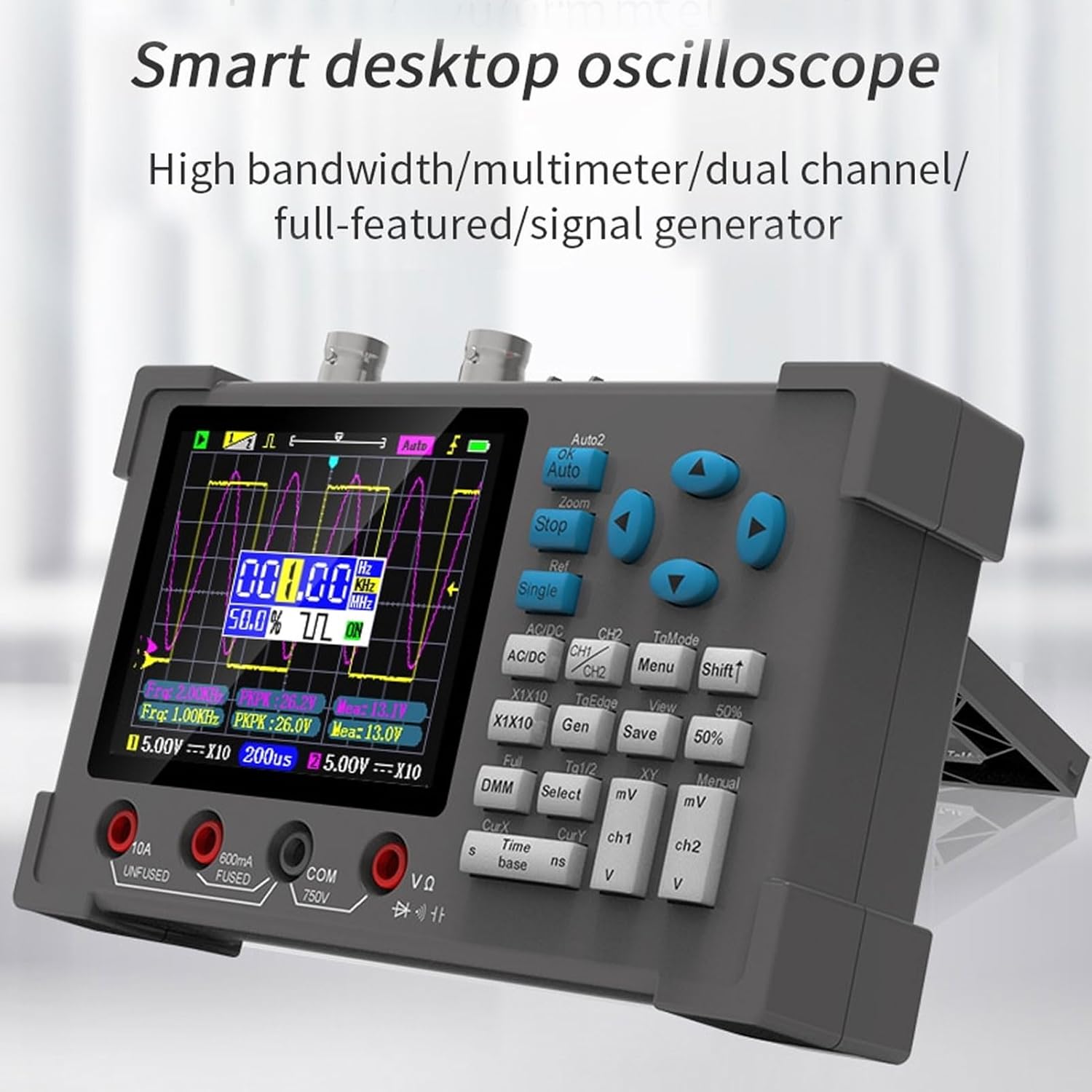
Figure 1.1: The DSO3D12 Smart Desktop Oscilloscope, showcasing its compact design and integrated display.
2. Safety Information
Please read all safety warnings and operating instructions carefully before using this product. Failure to follow these instructions may result in electric shock, fire, or serious injury.
- Do not exceed the maximum input voltage ratings specified in the technical specifications.
- Ensure proper grounding when connecting to circuits.
- Do not operate the device in wet or damp conditions.
- Do not attempt to disassemble or modify the device. Refer all servicing to qualified personnel.
- Use only the specified power adapter and accessories.
- Always disconnect test leads from the circuit before changing functions or ranges.
3. Product Overview
3.1. Key Features
- 3-in-1 Functionality: Digital Oscilloscope, Multimeter, and Signal Generator.
- Oscilloscope: Dual channel, 120MHz bandwidth (60MHz dual channel), 250MSa/s real-time sampling rate.
- Multimeter: Measures AC/DC voltage, AC/DC current, resistance, capacitance, diode, and continuity.
- Signal Generator: Outputs sine, square, triangle, and other waveforms with adjustable frequency (0-2MHz) and duty cycle (1-99% for square wave).
- Display: 3.2-inch high-definition IPS display with full viewing angle.
- Trigger Modes: Auto, Normal, Single.
- Measurement Functions: 14 types of automatic measurements, cursor measurement (X and Y).
- Waveform Storage: One-click save and view of screen waveforms.
3.2. Device Layout

Figure 3.1: Front view of the DSO3D12, showing the display, control buttons, and input terminals.
- IPS Display: 3.2-inch screen for waveform display and measurement readings.
- Control Buttons: Navigation, function selection, and parameter adjustment.
- BNC Connectors (CH1, CH2): Inputs for oscilloscope probes.
- Multimeter Input Terminals:
- 10A UNFUSED: 10A current input (unfused).
- 600mA FUSED: 600mA current input (fused).
- COM: Common terminal for multimeter measurements.
- VΩ: Voltage, Resistance, Diode, Capacitance, Continuity input.
- Signal Generator Output: Output for waveform generation.
- USB Type-C Port: For charging and data transfer.

Figure 3.2: Dimensions of the DSO3D12, illustrating its compact size for portability.
4. Specifications
| Feature | Specification |
|---|---|
| Model | Eujgoovsw9aeqzvy6 |
| Display | 3.2-inch IPS Display |
| Oscilloscope Bandwidth | 120MHz (Single Channel), 60MHz (Dual Channel) |
| Sampling Rate | 250MSa/s |
| Input Impedance | 1 MΩ |
| Time Base Range | 5 ns - 10 s |
| Vertical Sensitivity | 10 mV/div - 10 V/div |
| Max Input Voltage | ±40V (x1), ±400V (x10) |
| Trigger Modes | Auto, Normal, Single |
| Trigger Types | Rising Edge, Falling Edge |
| Coupling | AC, DC |
| Multimeter DC Voltage | 600mV, 6.00V, 60.0V, 600V, 750V (±0.5%+3) |
| Multimeter AC Voltage | 600mV, 6.00V, 60.0V, 600V (±1%+3) |
| Multimeter DC Current | 600mA, 10A (±2%+5) |
| Multimeter AC Current | 600mA, 10A (±3%+5) |
| Multimeter Resistance | 600Ω to 60MΩ (various accuracies) |
| Multimeter Capacitance | 60.00nF to 600.0μF (various accuracies) |
| Signal Generator Output Voltage | 2.5V ±0.05 |
| Signal Generator Frequency | 0-2MHz (Sine), 0-1MHz (Others) |
| Battery Type | 2500mAh Rechargeable Lithium Battery (Built-in) |
| Charging Port | Type-C 5V |
| Dimensions | 22.6 x 15.4 x 7.3 cm |
| Weight | 600 grams |
5. Setup
5.1. Unpacking and Inspection
Upon receiving your DSO3D12, carefully unpack all components and inspect for any signs of damage.
- DSO3D12 Main Unit
- Oscilloscope Probes (x2)
- Multimeter Test Leads
- USB Type-C Charging Cable
- User Manual (this document)

Figure 5.1: The DSO3D12 unit along with its standard accessories, including probes and test leads.
5.2. Charging the Device
The DSO3D12 comes with a built-in rechargeable lithium battery. Before first use, it is recommended to fully charge the device.
- Connect the provided USB Type-C cable to the device's charging port.
- Connect the other end of the USB cable to a 5V USB power adapter (not included) or a computer USB port.
- The charging indicator on the device will show the charging status.
- Once fully charged, disconnect the charging cable.
5.3. Powering On/Off
To power on the device, press and hold the power button until the screen illuminates. To power off, press and hold the power button again until the screen turns off.
6. Operating Instructions
6.1. Oscilloscope Mode
The oscilloscope function allows for the visualization and analysis of electrical signals.
- Connect the oscilloscope probes to the BNC connectors (CH1 or CH2) on the device.
- Attach the probe to the circuit point you wish to measure. Ensure the probe's ground clip is connected to the circuit's ground.
- Press the AC/DC button to select AC or DC coupling.
- Use the mV and V buttons to adjust the vertical sensitivity (Volts/division).
- Use the s and ns buttons to adjust the time base (Seconds/division).
- Press Auto for automatic signal detection and range adjustment.
- Use the navigation buttons to manually adjust waveform position and zoom.

Figure 6.1: The clear 3.2-inch HD IPS display, showing a typical oscilloscope waveform with measurement parameters.
6.1.1. Trigger Settings
Triggering stabilizes repetitive waveforms.
- Auto: Automatically triggers on a stable signal.
- Normal: Triggers only when the signal meets the set conditions. If no trigger condition is met, the display will not update.
- Single: Captures a single waveform when the trigger condition is met, then stops.
- Use the TgEdge button to select rising or falling edge trigger.
6.1.2. Cursor Measurement
Cursor measurement allows for precise measurement of waveform parameters.

Figure 6.2: Demonstrating the cursor measurement feature, allowing users to precisely measure points on the waveform.
- Press the CurX button to activate horizontal (time) cursors.
- Press the CurY button to activate vertical (voltage) cursors.
- Use the navigation buttons to move the cursors and read the corresponding values displayed on the screen.
6.1.3. XY Mode
XY mode displays the relationship between two input signals, often used for Lissajous figures to determine phase differences or frequency ratios.

Figure 6.3: Examples of Lissajous figures displayed in XY mode, illustrating the relationship between two input signals.
- Connect signals to both CH1 and CH2.
- Press the XY button to switch to XY mode.
6.1.4. Waveform Save/View
The device allows you to save and review captured waveforms.
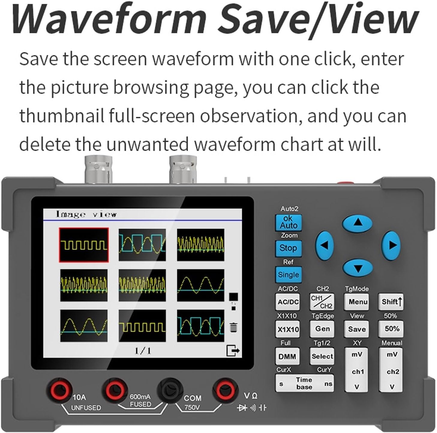
Figure 6.4: The waveform save and view interface, showing thumbnails of saved waveforms for easy browsing and management.
- Press the Save button to save the current waveform displayed on the screen.
- Press the View button to enter the waveform browsing page.
- Navigate through saved waveforms using the control buttons. You can view them in full screen or delete unwanted waveforms.
6.2. Multimeter Mode
The integrated multimeter provides precise measurements of various electrical parameters.
- Connect the multimeter test leads to the appropriate input terminals (COM, VΩ, 600mA FUSED, 10A UNFUSED).
- Press the DMM button to switch to multimeter mode.
- Use the Select button to cycle through different measurement functions (DC Voltage, AC Voltage, DC Current, AC Current, Resistance, Capacitance, Diode, Continuity).
- Connect the test leads to the circuit or component under test.
- Read the measurement value displayed on the screen.

Figure 6.5: Various multimeter display modes, including full-screen numerical readings and function selection interface.
Note: When measuring low voltage, resistance, or continuity, both oscilloscope and multimeter functions can be used simultaneously.
6.3. Signal Generator Mode
The built-in signal generator can output various waveforms for testing and calibration.
- Connect a test lead from the signal generator output terminal to the circuit or device you wish to input the signal to.
- Press the Gen button to enter signal generator mode.
- Use the navigation buttons to select the desired waveform type (sine, square, triangle, etc.).
- Adjust the frequency using the appropriate controls.
- For square waves, adjust the duty cycle as needed.
- The output voltage amplitude is fixed at 2.5V.
7. Maintenance
7.1. Cleaning
To maintain the device's performance and appearance, clean it regularly.
- Wipe the exterior with a soft, damp cloth.
- Do not use abrasive cleaners or solvents.
- Ensure no liquid enters the device.
7.2. Battery Care
The built-in lithium battery requires proper care for longevity.
- Charge the device regularly, even if not in frequent use, to prevent deep discharge.
- Avoid exposing the device to extreme temperatures.
- If storing for an extended period, charge the battery to approximately 50% before storage.
7.3. Storage
Store the device in a cool, dry place, away from direct sunlight and corrosive gases.
8. Troubleshooting
| Problem | Possible Cause | Solution |
|---|---|---|
| Device does not power on. | Battery is depleted. | Charge the device using the USB Type-C cable. |
| No waveform displayed in oscilloscope mode. |
|
|
| Multimeter readings are inaccurate. |
|
|
| Signal generator output is not as expected. |
|
|
9. Warranty and Support
This product is manufactured by Eujgoov. For warranty information and technical support, please refer to the purchase platform or contact the seller directly. Keep your purchase receipt as proof of purchase.
For common questions and troubleshooting, please refer to the relevant sections of this manual.