
1. Introduction
The IP-COM G1050F is an unmanaged Gigabit Ethernet switch designed for high-density, high-speed wired network creation. It is suitable for various environments such as businesses, parks, schools, and internet cafes, providing a straightforward, cost-effective, and fast internet access solution for video surveillance and small to medium-sized enterprise (SME) networks.
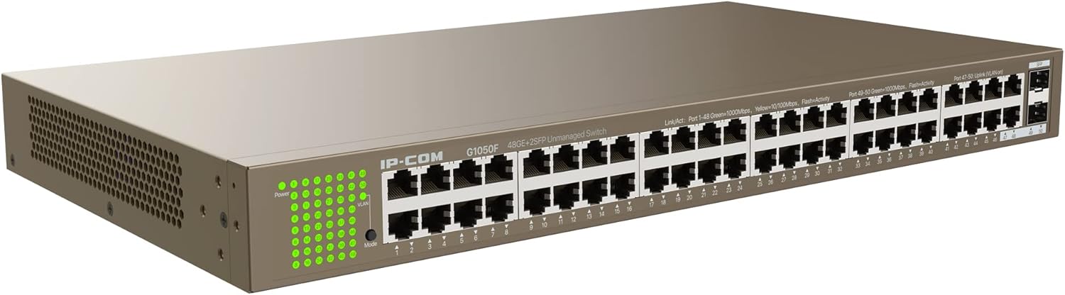
Image 1.1: Overall view of the IP-COM G1050F 48-Port Gigabit Ethernet Switch. This image shows the full chassis of the switch from an angled perspective, highlighting its compact 1U design and the array of network ports on the front panel.
This manual provides detailed instructions for the installation, operation, and maintenance of the G1050F switch. Please read this manual thoroughly before using the product to ensure proper setup and functionality.
2. Product Overview
2.1 Key Features
- High-Speed Connectivity: Equipped with 48 RJ45 10/100/1000Mbps ports and 2 independent 1000Mbps SFP slots for flexible network expansion.
- Long-Distance Transmission: SFP slots support long-distance fiber optic connections up to 20 km with compatible IP-COM SFP modules.
- Full-Duplex Performance: Achieves a full-duplex transmission speed of up to 2000 Mbps, ensuring rapid transfer of large files and smooth video streaming.
- Robust Protection: Integrated professional lightning protection circuit provides 6 kV protection for the built-in power supply and all Ethernet ports, enhancing stability and reliability.
- Flexible Installation: Supports desktop, rack-mount (standard 19" 1U design), and wall-mount installations.
- Plug & Play: Simplifies setup with automatic MDI/MDIX support, requiring no complex configuration.
- Standard Compliance: Conforms to IEEE 802.3, IEEE 802.3u, IEEE 802.3ab, IEEE 802.3z, and IEEE 802.3x standards.
2.2 Package Contents
Verify the package contents upon unpacking. If any item is missing or damaged, contact your vendor.
- IP-COM G1050F Gigabit Ethernet Switch
- Power Cord
- Rack-mount Kit (brackets and screws)
- User Manual (this document)
3. Hardware Description
3.1 Front Panel
The front panel of the G1050F switch features all network ports and LED indicators for status monitoring.

Image 3.1: Front view of the IP-COM G1050F switch. This image displays the 48 Gigabit Ethernet RJ45 ports, numbered 1 through 48, and the two SFP uplink ports, labeled 49 and 50. LED indicators for power, link/activity, and mode are visible on the left side.
- RJ45 Ports (1-48): 10/100/1000 Mbps auto-negotiation ports for connecting network devices such as computers, servers, and other switches.
- SFP Ports (49-50): 1000 Mbps Base-X SFP slots for fiber optic connections, typically used for uplinks to core networks or other switches over longer distances.
- LED Indicators: Provide visual status of the switch and its ports.
3.2 Rear Panel
The rear panel contains the power input and grounding point.

Image 3.2: Rear view of the IP-COM G1050F switch. This image shows the standard AC power input connector on the right side and a grounding screw to its left.
- AC-IN: Power receptacle for connecting the provided AC power cord.
- Grounding Screw: For connecting a grounding wire to protect against electrical surges.
3.3 LED Indicators
The LEDs on the front panel provide real-time status information:
| LED Name | Status | Description |
|---|---|---|
| Power | Green (On) | The switch is powered on. |
| Off | The switch is powered off. | |
| Link/Act (RJ45) | Green (On) | A 1000 Mbps link is established. |
| Green (Flashing) | Data is being transmitted or received at 1000 Mbps. | |
| Yellow (On) | A 10/100 Mbps link is established. | |
| Yellow (Flashing) | Data is being transmitted or received at 10/100 Mbps. | |
| Off | No device is connected or the link is down. | |
| Link/Act (SFP) | Green (On) | A 1000 Mbps SFP link is established. |
| Green (Flashing) | Data is being transmitted or received via SFP. | |
| Off | No SFP module is inserted or the link is down. | |
| Mode | Green (On) | Indicates the current operating mode (e.g., standard, VLAN). Refer to specific product documentation for mode details if applicable. |
4. Setup and Installation
4.1 Safety Precautions
- Ensure the power supply voltage matches the switch's requirements.
- Do not block ventilation openings. Ensure adequate airflow around the switch.
- Avoid placing the switch in direct sunlight, near heat sources, or in areas with high humidity or dust.
- Connect the grounding screw to a proper ground to prevent electrical damage.
4.2 Mounting Options
The G1050F switch supports three installation methods:
- Desktop Placement: Place the switch on a flat, stable surface. Ensure sufficient space for ventilation.
- Rack-Mount Installation: Use the provided rack-mount kit to install the switch into a standard 19-inch equipment rack. Secure the brackets to the switch sides with screws, then mount the switch into the rack.
- Wall-Mount Installation: If applicable, use appropriate wall-mounting hardware (not always included) to secure the switch to a wall. Ensure the wall can support the switch's weight.
4.3 Connecting the Switch
- Power Connection: Connect one end of the power cord to the AC-IN port on the rear panel of the switch and the other end to a standard power outlet.
- Network Device Connection (RJ45): Connect your network devices (e.g., computers, printers, IP cameras, access points) to any of the 48 RJ45 ports using standard Ethernet cables. The switch supports auto MDI/MDIX, so straight-through or crossover cables can be used.
- Uplink Connection (SFP): Insert compatible SFP modules into the SFP slots (49-50). Connect fiber optic cables from the SFP modules to other network devices (e.g., core switch, server) for long-distance or high-bandwidth uplinks.
- Power On: Once all connections are secure, power on the switch. The Power LED should illuminate.
5. Operating Instructions
The IP-COM G1050F is an unmanaged switch, meaning it operates on a plug-and-play basis without requiring complex software configuration. Once powered on and connected, it automatically forwards data between connected devices.
5.1 Basic Operation
- Ensure all devices connected to the switch are powered on and configured for network access.
- Observe the Link/Act LEDs on the switch. A solid green or yellow light indicates a successful link, while a flashing light indicates data activity.
- The switch automatically learns MAC addresses and forwards frames based on destination MAC addresses, optimizing network traffic.
5.2 Network Configuration Example
The G1050F can be integrated into various network topologies. Below is an example of how the switch can be deployed in a typical network environment.

Image 5.1: Example network topology. This diagram illustrates the IP-COM G1050F switch acting as a central distribution point, connecting to the internet via a router, directly to servers, and to other smaller switches (G1016G, G1008, G1005) which then connect to end devices like phones, computers, and surveillance cameras. Blue lines represent 1000M Ethernet cables, and orange lines represent 1000M fiber cables.
In this example:
- The G1050F connects to the Internet router, providing uplink connectivity.
- Servers are directly connected to the G1050F, potentially using SFP ports for high-bandwidth connections.
- Other smaller switches (G1016G, G1008, G1005) are connected to the G1050F, extending the network to various departments or areas.
- End devices such as IP phones, desktop computers, and surveillance cameras are connected to these smaller switches.
6. Specifications
| Feature | Description |
|---|---|
| Model | G1050F |
| Ports | 48 x 10/100/1000 Mbps Base-T RJ45 ports, 2 x 1000 Mbps Base-X SFP ports |
| Standards | IEEE 802.3, IEEE 802.3u, IEEE 802.3ab, IEEE 802.3z, IEEE 802.3x |
| Switching Capacity | 100 Gbps |
| Forwarding Rate | 74.4 Mpps |
| MAC Address Table | 16K |
| Jumbo Frame | 10K Bytes |
| Lightning Protection | 6 kV for power and all Ethernet ports |
| Dimensions (L x W x H) | 440 mm x 240 mm x 44 mm |
| Power Supply | Internal AC power supply (100-240V AC, 50/60Hz) |
| Operating Temperature | 0°C to 45°C (32°F to 113°F) |
| Storage Temperature | -40°C to 70°C (-40°F to 158°F) |
| Operating Humidity | 10% to 90% non-condensing |
Note: Specifications are subject to change without prior notice.
7. Troubleshooting
This section addresses common issues you might encounter with the G1050F switch.
7.1 No Power
- Check Power Cord: Ensure the power cord is securely connected to both the switch's AC-IN port and a working power outlet.
- Verify Power Outlet: Test the power outlet with another device to confirm it is supplying power.
- Check Power LED: If the Power LED is off, the switch is not receiving power.
7.2 No Link on a Port
- Check Cable Connection: Ensure the Ethernet cable (or SFP module and fiber cable) is securely connected to both the switch port and the connected device.
- Verify Cable Integrity: Test the cable with another device or replace it to rule out a faulty cable.
- Check Connected Device: Ensure the connected device (e.g., computer, server) is powered on and its network adapter is functioning correctly.
- Check Link/Act LED: If the Link/Act LED for the port is off, there is no active link.
- SFP Module Check: For SFP ports, ensure the SFP module is correctly inserted and compatible, and the fiber cable is not damaged.
7.3 Slow Network Speed
- Check Cable Type: Ensure you are using Cat5e or Cat6 Ethernet cables for Gigabit speeds. Older Cat5 cables may limit speed.
- Verify Link Speed: Check the Link/Act LED color. Yellow indicates 10/100 Mbps, while green indicates 1000 Mbps. If it's yellow, the connected device or cable might be limiting the speed.
- Network Congestion: High network traffic can cause slowdowns. Monitor network usage to identify potential bottlenecks.
- Device Capabilities: Ensure all connected devices support Gigabit Ethernet for optimal performance.
8. Maintenance
- Regular Cleaning: Keep the switch clean and free of dust. Use a soft, dry cloth. Do not use liquid cleaners.
- Ventilation: Ensure the ventilation holes are not obstructed to prevent overheating.
- Firmware Updates: While this is an unmanaged switch, periodically check the manufacturer's website for any available firmware updates, though they are less common for unmanaged devices.
- Environmental Conditions: Operate the switch within the specified temperature and humidity ranges to ensure longevity.
9. Safety Information
- Do not open the switch casing. There are no user-serviceable parts inside.
- Disconnect power before cleaning or moving the switch.
- Avoid spilling liquids on the switch.
- Ensure proper grounding to prevent electrical hazards.
- Dispose of the product responsibly according to local regulations at the end of its life cycle.
10. Warranty and Support
Information regarding specific warranty terms and technical support for the IP-COM G1050F switch is not provided within the product details. Please refer to the official IP-COM website or contact your local distributor for warranty details and support options.
For further assistance, you may visit the IP-COM official website (link provided as an example, actual link may vary by region).


