
Telituny NY-D01
Telituny 40A Spot Welding Machine Control Board NY-D01 Instruction Manual
Model: NY-D01 | Brand: Telituny
1. Introduction
This instruction manual provides essential information for the safe and effective use of the Telituny 40A Spot Welding Machine Control Board NY-D01. This control board is designed for DIY resistance spot welding applications, offering adjustable time and current control. Please read this manual thoroughly before installation and operation.
2. Safety Information
Warning: Spot welding involves high currents and voltages. Improper use can lead to electric shock, burns, or fire. Always follow safety precautions.
- Ensure all connections are secure and properly insulated.
- Disconnect power before making any adjustments or maintenance.
- Wear appropriate personal protective equipment (PPE), including safety glasses and gloves.
- Operate in a well-ventilated area.
- This device is intended for experienced users or under professional supervision.
3. Product Overview
The Telituny NY-D01 control board is a compact and reliable solution for DIY spot welding. It features an STM8 industrial control microcontroller for precise timing and current regulation. The design incorporates optocouplers for isolation between strong and weak current circuits, enhancing operational safety.

Image 3.1: Components of the Telituny NY-D01 Spot Welding Machine Control Board, including the main board, display panel, connection cable, nuts, and washers.

Image 3.2: Detailed view of the Telituny NY-D01 control board and its display panel, highlighting the overall structure and connections. This board is compatible with 40A thyristors.
Key Features:
- STM8 industrial control microcontroller for precise operation.
- Optocoupler isolation for enhanced safety between strong and weak current circuits.
- High-precision potentiometers for adjustable time and current input.
- Clear indicators for power, state, foot switch, and trigger.
- Reliable zero-crossing detection circuit for accurate SCR phase shift.
- Quick-connect bolt terminals for power and foot switch lines.
4. Specifications
| Feature | Detail |
|---|---|
| Model | NY-D01 |
| Material | PCB |
| Current Rating | 40A (compatible with 40A thyristors) |
| Control Microcontroller | STM8 Industrial Control Center Microcontroller |
| Isolation | Optocoupler isolation for strong and weak currents |
| Input Adjustment | High-precision potentiometers for time and current |
| Dimensions (Main Board) | Approx. 80mm x 60mm (3.1in x 2.4in) |
| Weight | Approx. 80g |

Image 4.1: Physical dimensions of the Telituny NY-D01 control board, showing approximate measurements of 80mm by 60mm.
5. Setup and Wiring
Proper wiring is crucial for the safe and correct operation of the spot welding machine. Refer to the wiring diagram below for connection details. Ensure all power is disconnected before beginning installation.
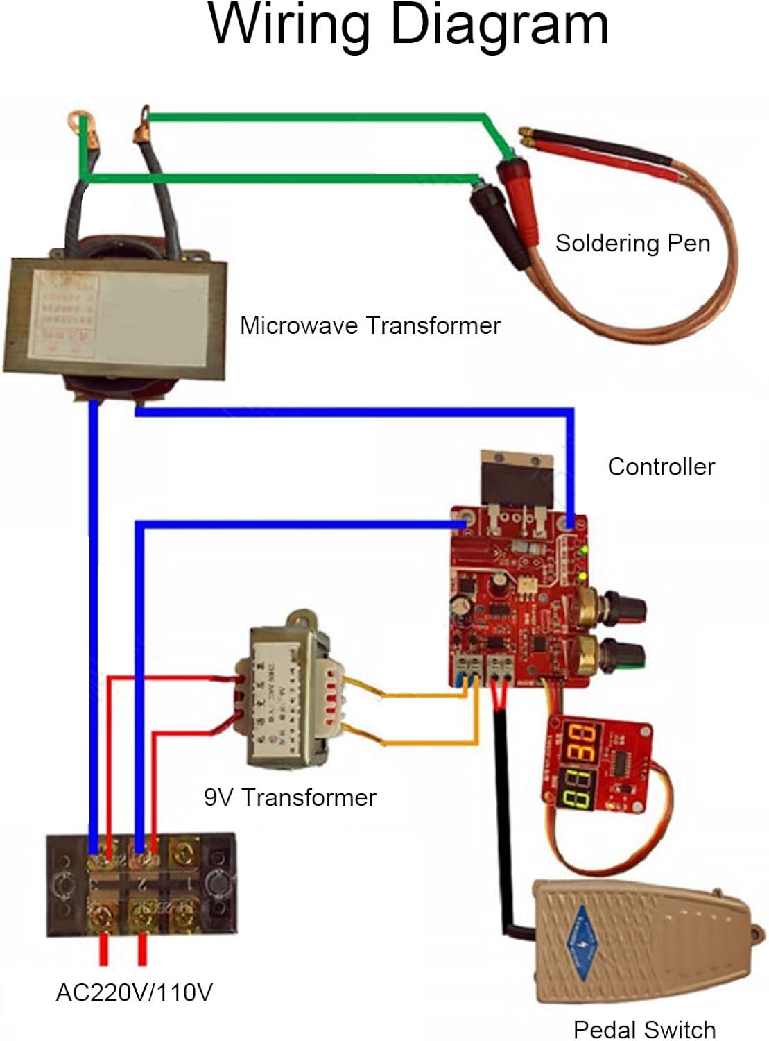
Image 5.1: Wiring diagram illustrating the connections for the Telituny NY-D01 control board, including the microwave transformer, soldering pen, 9V transformer, AC power input (AC220V/110V), and pedal switch.
Connection Steps:
- Connect the Main Power: Connect the AC220V/110V power source to the primary side of the microwave transformer and the 9V transformer.
- Connect the 9V Transformer: The output of the 9V transformer powers the control board. Connect its output to the designated 9V input terminals on the control board.
- Connect the Microwave Transformer Secondary: Connect the secondary winding of the microwave transformer to the soldering pen.
- Connect the Control Board to the Main Circuit: The control board regulates the primary side of the microwave transformer. Connect the control board's output to the appropriate terminals controlling the microwave transformer's primary circuit.
- Connect the Pedal Switch: Connect the pedal switch to the dedicated terminals on the control board. This switch will trigger the welding process.
- Connect the Display Panel: Use the provided cable to connect the display panel to the main control board.
Note: The power line and foot switch line utilize screw-free quick connection terminals for convenience and reliability. Double-check all connections before applying power.

Image 5.2: An example of the Telituny NY-D01 control board installed within a spot welding machine, showing various wire connections.
6. Operating Instructions
Once the control board is correctly wired and powered, you can adjust the welding parameters using the potentiometers.
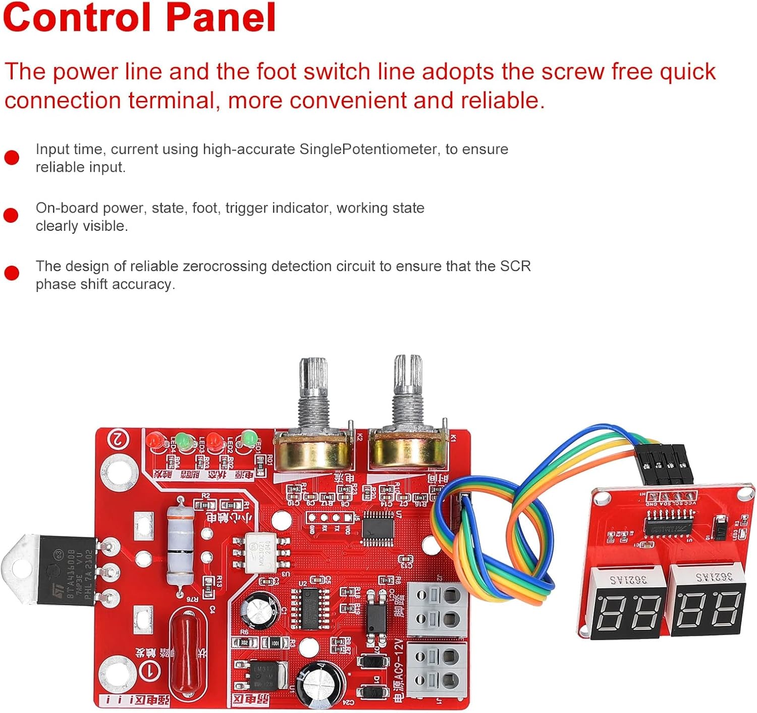
Image 6.1: The control panel of the Telituny NY-D01, featuring two potentiometers for adjustment and a digital display for showing parameters.
Adjusting Parameters:
- Time Adjustment: Use the potentiometer labeled for time to set the duration of the welding pulse. The display will show the set time.
- Current Adjustment: Use the potentiometer labeled for current to adjust the welding current intensity. The display will show the current setting.
- Indicators: Observe the on-board LEDs for power, state, foot switch activation, and trigger status. These provide visual feedback on the board's operation.
Experiment with different time and current settings on scrap material to achieve the desired weld quality for your specific application. Always start with lower settings and gradually increase as needed.
7. Maintenance
To ensure the longevity and reliable performance of your Telituny NY-D01 control board, follow these maintenance guidelines:
- Cleaning: Keep the board free from dust, debris, and moisture. Use a soft, dry brush or compressed air for cleaning.
- Inspection: Periodically inspect all wiring connections for tightness and signs of wear or damage.
- Storage: When not in use, store the control board in a dry, cool environment, away from direct sunlight and corrosive substances.
- Avoid Overloading: Do not exceed the specified current rating of 40A to prevent damage to the board and associated components.
8. Troubleshooting
If you encounter issues with your Telituny NY-D01 control board, refer to the following common problems and solutions:
| Problem | Possible Cause | Solution |
|---|---|---|
| Board does not power on. | No power supply; incorrect 9V transformer connection. | Check main power and 9V transformer connections. Ensure 9V supply is active. |
| No welding output. | Incorrect wiring to microwave transformer; faulty pedal switch; incorrect time/current settings. | Verify wiring according to diagram. Test pedal switch. Adjust time and current settings. |
| Inconsistent welding. | Loose connections; unstable power supply; component overheating. | Check all connections. Ensure stable power. Allow board to cool if signs of overheating are present. |
| Display not working. | Loose display cable; faulty display unit. | Ensure display cable is securely connected. If problem persists, the display unit may need replacement. |
If the problem persists after attempting these solutions, contact Telituny customer support or a qualified technician.
9. Warranty and Support
Telituny products are designed for reliability and performance. For specific warranty details, please refer to the product packaging or the seller's terms of sale. For technical support or inquiries, please contact your retailer or visit the official Telituny website.
Manufacturer: Telituny
Model: NY-D01
Ask a question about this manual
Ask about setup, troubleshooting, compatibility, parts, safety, or missing instructions. Manuals+ will review the question and use this page’s manual context to help answer it.