1. Introduction
This manual provides essential information for the safe and effective use of NuNeth 10-pin signal relays, including models A5W-K, A12W-K, and A24W-K. These relays are designed for various switching applications in electronic circuits. Please read this manual thoroughly before installation and operation.
2. Safety Information
WARNING: Electrical components can cause electric shock or injury if not handled properly. Always follow safety precautions.
- Ensure power is disconnected before installing, wiring, or servicing the relay.
- Only qualified personnel should perform installation and wiring.
- Verify correct voltage and current ratings before connecting the relay to a circuit.
- Do not exceed the specified maximum switching voltage or current.
- Avoid touching relay terminals while power is applied.
3. Product Overview
The NuNeth 10-pin signal relays are compact, reliable components used for switching low-level signals in various electronic applications. They feature a standard pin configuration for easy integration into printed circuit boards (PCBs).
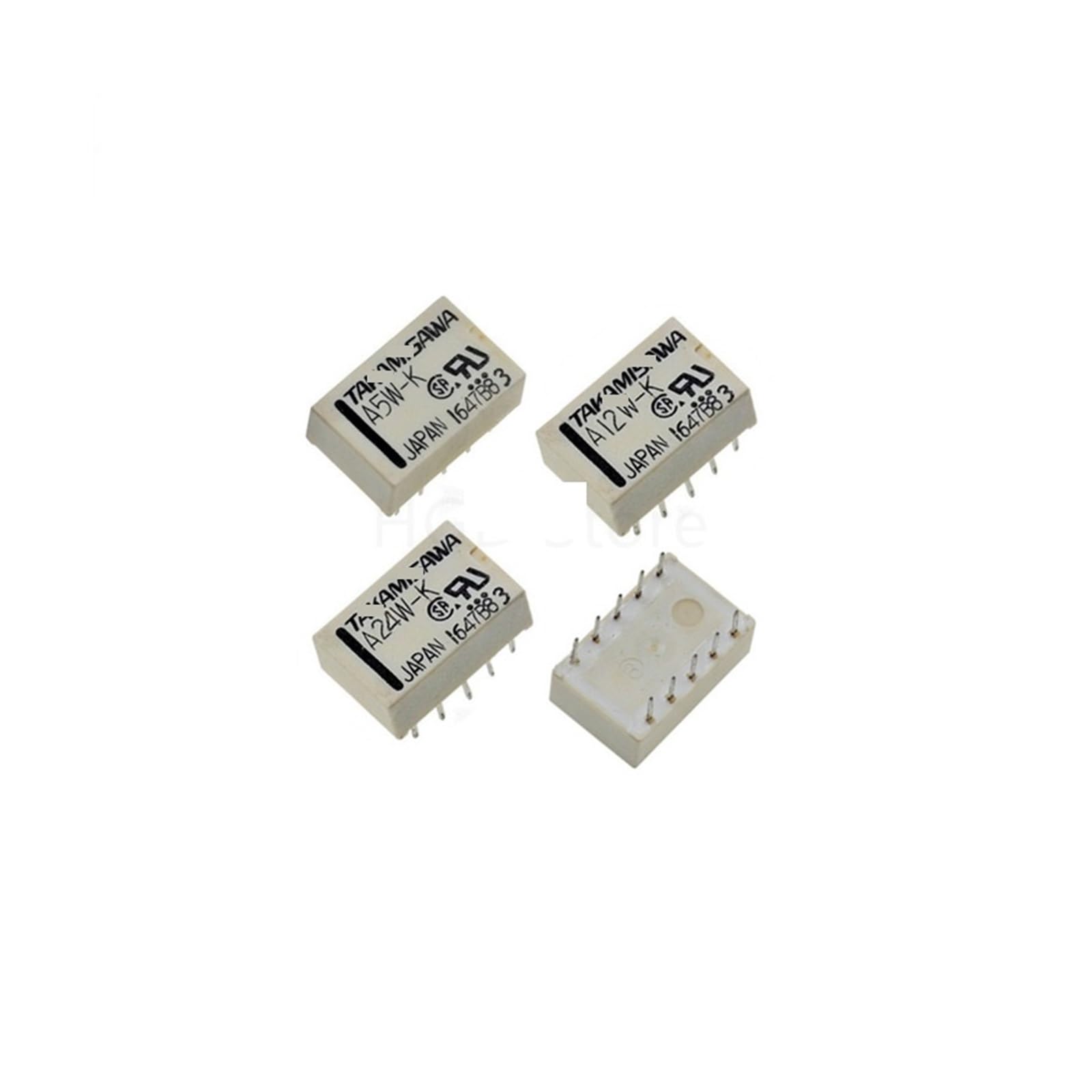
Figure 3.1: Top view of a generic 10-pin signal relay, illustrating the physical layout and pin configuration for circuit board mounting.

Figure 3.2: Bottom view of a 10-pin signal relay, highlighting the solderable pins for connection to a PCB or socket.

Figure 3.3: A NuNeth A5W-K 5VDC signal relay, showing the model designation and manufacturer markings on its casing.
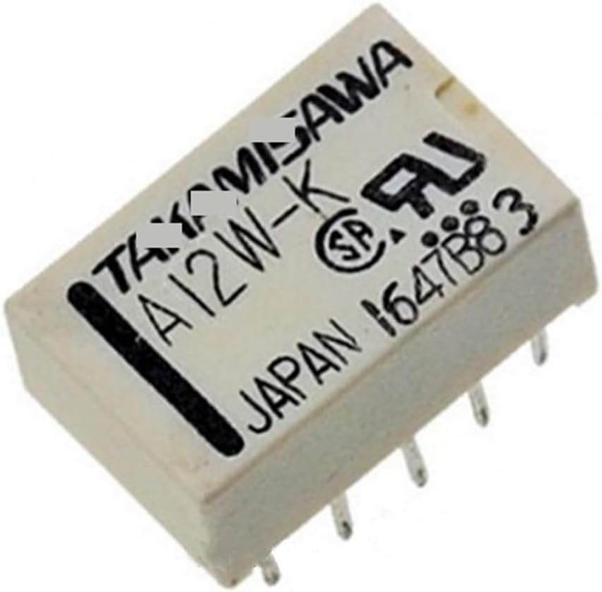
Figure 3.4: A NuNeth A12W-K 12VDC signal relay, identifiable by its model number printed on the top surface.

Figure 3.5: A NuNeth A24W-K 24VDC signal relay, clearly showing the model and voltage rating.

Figure 3.6: A collection of NuNeth A5W-K and A12W-K signal relays, demonstrating their compact size and consistent form factor.
4. Specifications
The following table outlines the general specifications for the NuNeth 10-pin signal relays. Specific characteristics may vary slightly between models (A5W-K, A12W-K, A24W-K) primarily in coil voltage.
| Feature | A5W-K (5VDC) | A12W-K (12VDC) | A24W-K (24VDC) |
|---|---|---|---|
| Coil Voltage | 5V DC | 12V DC | 24V DC |
| Contact Form | DPDT (Double Pole Double Throw) - 2 Form C | ||
| Number of Pins | 10 Pins | ||
| Max. Switching Current | Typically 1A - 2A (refer to specific datasheet for exact value) | ||
| Max. Switching Voltage | Typically 125V AC / 30V DC (refer to specific datasheet for exact value) | ||
| Operating Temperature | Typically -40°C to +70°C | ||
| Insulation Resistance | 100 MΩ min. (at 500V DC) | ||
| Dielectric Strength | Coil to Contact: 1000V AC, Contact to Contact: 750V AC | ||
| Dimensions (Approx.) | Length: 20mm, Width: 10mm, Height: 12mm (excluding pins) | ||
| Weight | Approximately 1 gram (0.035 oz) per relay | ||
Note: These specifications are general. Always consult the specific datasheet for the exact model being used for critical applications.
5. Setup and Installation
Proper installation is crucial for the reliable operation of the signal relay. These relays are typically designed for through-hole mounting on a PCB or insertion into a compatible relay socket.
5.1 Pin Configuration
The 10-pin configuration typically includes pins for the coil and two sets of changeover contacts (DPDT). Refer to the relay's markings or datasheet for the exact pinout diagram. A common DPDT 10-pin relay pinout includes:
- Coil Pins: These pins energize the relay, typically requiring the specified DC voltage (5V, 12V, or 24V).
- Common (COM) Pins: These are the moving contacts.
- Normally Open (NO) Pins: These contacts are open when the coil is de-energized and close when energized.
- Normally Closed (NC) Pins: These contacts are closed when the coil is de-energized and open when energized.
Figure 5.1: Illustrative diagram of a 10-pin relay's underside, indicating where coil and contact pins are typically located. Always verify with the specific relay's datasheet.
5.2 Installation Steps
- Power Off: Disconnect all power from the circuit before beginning installation.
- Identify Pins: Carefully identify the coil pins and contact pins (COM, NO, NC) using the relay's markings or datasheet.
- Mounting: Insert the relay pins into the corresponding holes on the PCB or relay socket. Ensure correct orientation.
- Soldering (if applicable): If mounting directly to a PCB, solder the pins securely. Ensure good solder joints and avoid bridging pins.
- Wiring: Connect the coil to the appropriate control voltage source (e.g., 5V for A5W-K). Connect the load circuit to the contact pins (COM, NO, NC) as required by your application.
- Verification: Double-check all connections for correctness and security before applying power.
6. Operating Instructions
The operation of a signal relay is straightforward:
- De-energized State: When no voltage is applied to the coil, the common (COM) contacts are connected to the normally closed (NC) contacts. The normally open (NO) contacts remain open.
- Energized State: When the specified coil voltage (e.g., 5V for A5W-K) is applied to the coil pins, an electromagnetic field is generated. This field pulls the common (COM) contacts away from the NC contacts and connects them to the NO contacts.
- Switching: The relay acts as an electrical switch, allowing a low-power control signal (to the coil) to control a higher-power or isolated circuit (through the contacts).
Ensure the coil voltage matches the relay model (A5W-K for 5V, A12W-K for 12V, A24W-K for 24V) to prevent damage or improper operation.
7. Maintenance
NuNeth signal relays are generally maintenance-free components. However, observing the following can help ensure longevity:
- Keep Clean: Ensure the relay and its surrounding area are free from dust, dirt, and moisture, which can affect performance or cause short circuits.
- Inspect Connections: Periodically check for loose or corroded connections, especially in high-vibration environments.
- Avoid Overload: Do not exceed the relay's maximum switching current or voltage ratings, as this can lead to premature failure of the contacts.
- Environmental Conditions: Operate the relay within its specified temperature and humidity ranges.
8. Troubleshooting
If the relay is not functioning as expected, consider the following common issues and solutions:
| Problem | Possible Cause | Solution |
|---|---|---|
| Relay coil does not energize (no click sound) | Incorrect coil voltage; no voltage applied; reversed polarity (for DC coils); faulty coil. | Verify coil voltage matches relay specification (5V, 12V, 24V). Check power supply and wiring. Ensure correct polarity. Replace relay if coil is faulty. |
| Relay energizes but contacts do not switch load | Incorrect wiring of load; load current/voltage exceeds contact rating; damaged contacts. | Check load wiring to COM, NO, NC pins. Ensure load specifications are within relay contact ratings. Replace relay if contacts are visibly damaged or stuck. |
| Intermittent operation | Loose connections; unstable coil voltage; contact bounce; environmental factors. | Secure all wiring connections. Ensure stable power supply to the coil. Consider adding a snubber circuit if switching inductive loads. Check operating environment. |
| Relay gets excessively hot | Over-voltage to coil; excessive current through contacts; short circuit in load. | Verify coil voltage is correct. Ensure load current is within contact ratings. Check load for short circuits. Disconnect power immediately if overheating occurs. |
9. Warranty and Support
For specific warranty information or technical support regarding your NuNeth signal relays, please refer to the product packaging or contact your point of purchase. Keep your purchase receipt as proof of purchase.
For further assistance, you may also visit the NuNeth product page on Amazon.