1. Introduction
The LINOVISION POE Splitter (Model POE-SP01) is designed to split Power over Ethernet (PoE) into separate 10/100Mbps data and DC12V power outputs. This device allows you to power non-PoE compatible devices, such as security cameras, wireless access points, speakers, and VoIP phones, using a single Ethernet cable from an IEEE802.3af/at compliant PoE switch or injector. It simplifies cabling and provides a reliable power solution for various network devices.
2. Package Contents
Verify that all items are included in your package:
- 2 x LINOVISION POE Splitter (Model POE-SP01)
- 2 x DC 12V Connectors (for connecting devices with different DC port sizes)

Image: Package contents including two POE splitters and two DC connectors.

Image: Detailed view of the additional two-pin DC connector, illustrating its components and how to connect power cables.
3. Product Overview
The LINOVISION POE Splitter features a compact design with an RJ45 input port for PoE and two output cables: one for 10/100Mbps data and another for DC12V 2A power. It includes LED indicators for power and data status.
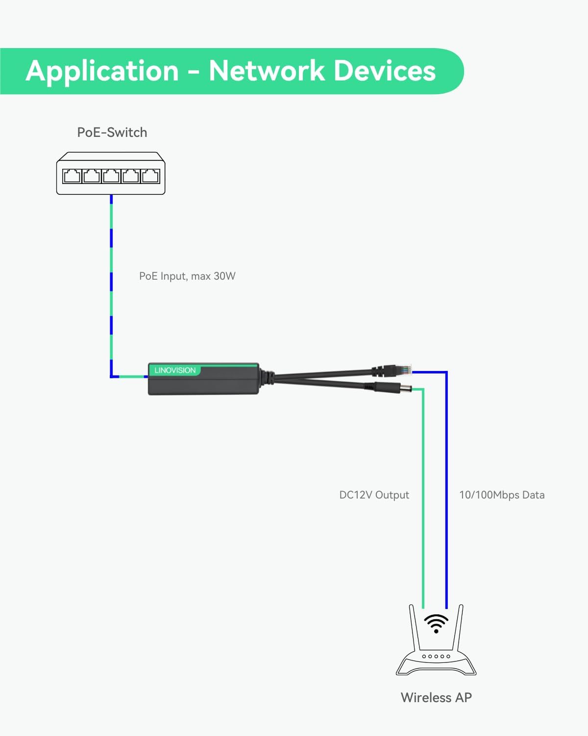
Image: Close-up view of the POE Splitter's RJ45 input and DC power output ports.

Image: Dimensions and weight of the LINOVISION POE Splitter.
4. Product Features
- 12V POE SPLITTER: Splits IEEE802.3af/at POE into 10/100Mbps Data and DC12V power outputs.
- DC OUTPUT: Provides DC12V 2A power output (plug size: 5.5 x 2.1mm) for non-PoE devices. Includes DC 12V connectors for versatile device compatibility.
- POE INPUT: Supports IEEE802.3af/at standard, including both Mode A and Mode B. Compatible with 44-57V DC voltage PoE switches/injectors.
- SURGE PROTECTION: Features 4KV surge protection to safeguard the PoE splitter and connected devices from lightning strikes and electrical surges, ensuring reliable performance in various environments.
- PLUG AND PLAY: No configuration required for easy installation and immediate use.

Image: The PoE splitter supports both Mode A and Mode B for broad compatibility with PoE power supply devices.

Image: Safety features including 4KV lightning protection, short circuit protection, and 3500V high-voltage isolation.
5. Setup & Connection
Follow these steps to connect your LINOVISION POE Splitter:
- Connect the RJ45 input port of the POE Splitter to an IEEE802.3af/at compliant PoE switch or PoE injector using an Ethernet cable.
- Connect the data output (RJ45) cable from the POE Splitter to the Ethernet input of your non-PoE device (e.g., IP camera, Wireless AP).
- Connect the DC12V power output cable from the POE Splitter to the DC power input of your non-PoE device. Use the provided DC 12V connectors if the device requires a different plug size.
- Ensure all connections are secure. The LED indicators on the splitter will illuminate to confirm power and data connectivity.
Video: An unboxing video for the LINOVISION POE Splitter with DC12V 2A Output, demonstrating the product and its components.
Image: Functional diagram of the DC12V PoE Splitter, illustrating the separation of PoE input into data and power outputs.
6. Applications
The LINOVISION POE Splitter is suitable for various applications where non-PoE devices need to be powered and connected to a network via PoE infrastructure.
6.1 Powering Non-PoE IP Cameras
Integrate your non-PoE IP cameras into a PoE network without needing separate power adapters. The splitter delivers both data and power over a single Ethernet cable.
Video: A demonstration of powering an IP camera using the LINOVISION PoE Splitter, showing the connection process and the camera powering on.

Image: Application diagram for connecting a non-PoE IP camera using the splitter.
6.2 Powering Wireless Access Points (APs)
Extend your wireless network by powering Wireless APs in locations without direct power outlets, utilizing existing PoE infrastructure.

Image: Application diagram for connecting a Wireless AP using the splitter.
6.3 Powering Two DC12V Devices
In certain scenarios, the splitter can provide power to two DC12V devices, such as an IP camera and an alarm, by utilizing the additional DC 12V connectors.

Image: Application diagram for connecting two DC12V devices (e.g., IP camera and alarm) using the splitter.
7. Specifications
| Model Number | POE-SP01 |
| POE Input Standard | IEEE802.3af/at |
| POE Input Voltage | 44-57V DC |
| DC Output Voltage | 12V DC |
| DC Output Current | 2A |
| DC Plug Size | 5.5 x 2.1mm |
| Data Transfer Rate | 10/100Mbps |
| Hardware Interface | Ethernet |
| Surge Protection | 4KV |
| Item Weight | 4.2 ounces (0.12 Kilograms) |
| Package Dimensions | 6.57 x 4.41 x 1.46 inches |
| Color | Black |
8. Troubleshooting
- No Power to Device:
- Ensure the PoE switch/injector is powered on and providing IEEE802.3af/at compliant PoE.
- Check all cable connections for proper seating.
- Verify the DC plug size and voltage requirements of your device match the splitter's output (DC12V 2A).
- No Data Connection:
- Confirm the Ethernet cable from the splitter's data output is securely connected to your device.
- Check the network status indicators on both the splitter and your device.
- Ensure the PoE switch/injector is functioning correctly.
- Intermittent Connectivity:
- Inspect Ethernet cables for damage.
- Ensure the environment is within the operating temperature range for the device.
- Verify the power draw of your connected device does not exceed 2A.
9. Warranty & Support
LINOVISION products typically come with a manufacturer's warranty. For specific warranty details, technical support, or service inquiries, please refer to the official LINOVISION website or contact their customer support directly. Keep your purchase receipt for warranty claims.


