1. Introduction
This manual provides detailed instructions for the installation, operation, and maintenance of the Xuulan JGA25-370 DC Gear Motor with Encoder. This high-torque gear motor is designed for various applications requiring precise speed control and robust performance, such as mini toy cars and other chassis motor systems. Please read this manual thoroughly before use to ensure proper function and longevity of the product.
2. Product Overview
The JGA25-370 DC Gear Motor features a compact design with an integrated encoder for speed measurement. It is engineered with precision winding technology, enhancing its power output and overall efficiency. The motor's construction emphasizes good toughness and impact resistance, contributing to improved bearing quality and extended service life.

Figure 1: Front view of the Xuulan JGA25-370 DC Gear Motor with integrated encoder and wiring harness.
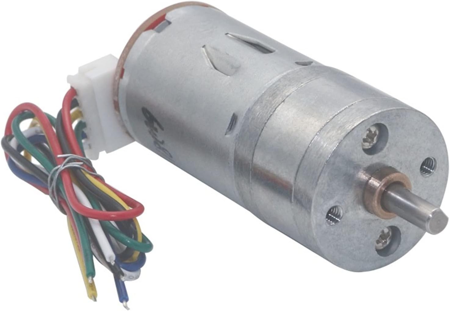
Figure 2: Side view of the JGA25-370 DC Gear Motor, showing the motor body and output shaft.
3. Specifications
The JGA25-370 series offers various RPM and voltage configurations. The specific model covered by this manual is the 24V, 35RPM variant.
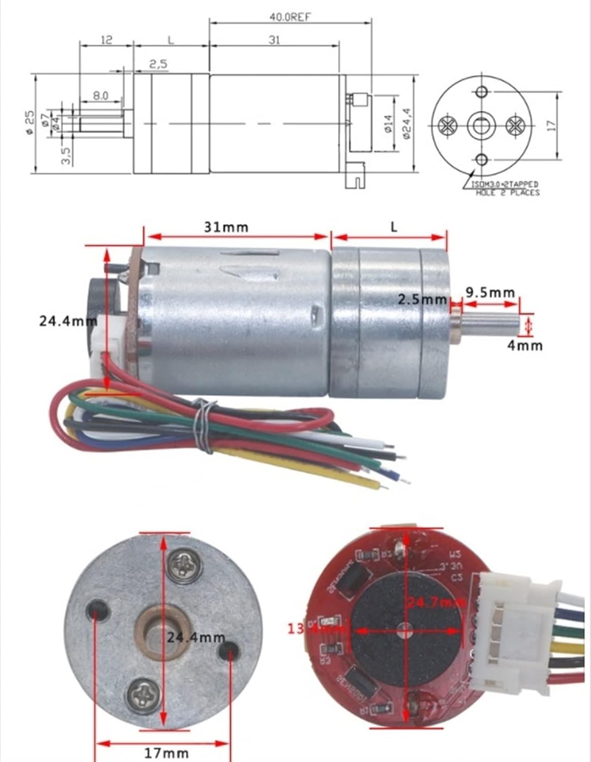
Figure 3: Technical drawing illustrating the dimensions and internal components of the JGA25-370 motor.
| Feature | Description |
|---|---|
| Model | JGA25-370 |
| Outer Diameter | 25mm |
| Shaft Length | 12mm (D8mm) |
| Shaft Out Length (without steps) | 9.8mm |
| Shaft Diameter | 4mm (D-shaped) |
| Weight | Approximately 93g (3.53 ounces) |
| Material | Copper |
| Voltage Options | 6V, 12V, 24V (This variant: 24V) |
| RPM Options | Various (This variant: 35RPM) |
| Encoder | Integrated, 11 signals per motor revolution |

Figure 4: Detailed performance parameters for various JGA25-370 motor configurations, including no-load and rated specifications.
4. Setup and Wiring
Careful wiring is essential for the correct operation of the motor and encoder. Refer to the wiring diagram below for connections.

Figure 5: Wiring diagram showing the color codes for motor power and encoder signals.
4.1 Wiring Connections
- Red Wire: Motor power + (Positive). Exchanging the polarity of the red and white wires controls the motor's forward and reverse direction.
- Black Wire: Coding power - (Negative).
- Yellow Wire: Signal feedback (11 signals per motor revolution).
- Green Wire: Signal feedback (11 signals per motor revolution).
- Blue Wire: Coding power + (Positive). Ensure correct polarity; connecting positive and negative poles incorrectly (e.g., 3.3-5V) can damage the encoder.
- White Wire: Motor power - (Negative). Exchanging the polarity of the red and white wires controls the motor's forward and reverse direction.
4.2 Mounting
Securely mount the motor using appropriate fasteners through the mounting holes on the motor's faceplate. Ensure the mounting surface is stable and can withstand the motor's torque and vibrations during operation. Avoid overtightening screws to prevent damage to the motor housing.
5. Operating Instructions
5.1 Power Supply
Connect the motor to a stable DC power supply matching the motor's rated voltage (e.g., 24V for this variant). Ensure the power supply can provide sufficient current for the motor's operation, especially under load.
5.2 Direction Control
The motor's direction of rotation can be reversed by swapping the polarity of the power connections to the red and white motor wires. For example, if red is connected to positive and white to negative for forward motion, reverse them for backward motion.
5.3 Encoder Feedback
The integrated encoder provides speed and position feedback. Connect the yellow and green signal wires to a compatible microcontroller or encoder interface. Each motor revolution generates 11 signals, allowing for precise speed and distance measurement in your application.
6. Maintenance
The JGA25-370 DC Gear Motor is designed for durability and requires minimal maintenance. However, adhering to the following guidelines can extend its lifespan:
- Keep Clean: Regularly clean the motor's exterior to prevent dust and debris accumulation, which can affect cooling and moving parts.
- Avoid Overload: Do not operate the motor beyond its rated torque and current specifications to prevent overheating and premature wear.
- Check Connections: Periodically inspect all wiring connections for looseness or damage. Secure any loose connections to prevent intermittent operation or electrical shorts.
- Environmental Conditions: Operate the motor within its specified temperature and humidity ranges. Avoid exposure to excessive moisture or corrosive environments.
7. Troubleshooting
If you encounter issues with your JGA25-370 motor, refer to the following troubleshooting tips:
| Problem | Possible Cause | Solution |
|---|---|---|
| Motor does not run | No power supply; Incorrect wiring; Damaged motor. | Check power connections and voltage; Verify wiring against diagram; Replace motor if damaged. |
| Motor runs but encoder has no output | Incorrect encoder wiring; Damaged encoder. | Verify encoder wiring (Blue/Black for power, Yellow/Green for signals); Replace motor if encoder is damaged. |
| Motor runs slowly or with reduced torque | Insufficient power supply; Overload; Mechanical obstruction. | Ensure power supply meets current requirements; Reduce load; Check for and remove any obstructions. |
| Motor makes unusual noise | Worn gears; Misalignment; Foreign objects. | Inspect gears for wear; Check mounting for proper alignment; Remove any foreign objects. |
8. Warranty and Support
For warranty information or technical support, please contact your retailer or the manufacturer directly. Keep your purchase receipt as proof of purchase. This product is designed for specific applications; improper use or modification may void the warranty.