1. Introduction
This manual provides detailed instructions for the installation, setup, operation, and maintenance of the Generic M5DCD Optiplex 390 Motherboard Systemboard. Please read this manual thoroughly before proceeding with installation or operation to ensure proper functionality and to prevent damage to the component or other system parts.
2. Safety Information
Observe the following safety precautions to prevent damage and ensure safe operation:
- Always disconnect the power supply from the computer before installing or removing any components.
- Wear an anti-static wrist strap or frequently touch a grounded metal object to discharge static electricity before handling the motherboard. Electrostatic discharge (ESD) can damage sensitive electronic components.
- Handle the motherboard by its edges to avoid touching components or circuits.
- Ensure proper ventilation within the computer case to prevent overheating.
- Keep the motherboard away from liquids and extreme temperatures.
3. Component Overview
The Generic M5DCD Optiplex 390 Motherboard Systemboard features various connectors and slots for essential computer components. Familiarize yourself with the layout before installation.
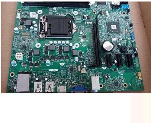
Image 1: Top-down view of the Generic M5DCD Optiplex 390 Motherboard Systemboard, showing the CPU socket, RAM slots, PCIe slots, SATA ports, and various I/O connectors.
Key Components:
- CPU Socket (LGA 1155): For Intel processors compatible with the LGA 1155 standard.
- RAM Slots (DDR3): Two slots for DDR3 memory modules.
- PCIe Slots: Expansion slots for graphics cards and other add-in cards.
- SATA Ports: Connectors for storage devices such as hard drives and solid-state drives.
- I/O Panel: Includes USB ports, video outputs (VGA), and audio jacks.
- 24-Pin ATX Power Connector: Main power input from the power supply.
- CMOS Battery: Powers the real-time clock and stores BIOS settings.
4. Installation
4.1. Unpacking
Carefully remove the motherboard from its packaging. Inspect for any visible damage. Retain all packaging materials for future use or return.
4.2. Preparing Your System
Ensure your computer case is compatible with the motherboard's form factor. Prepare the case by installing standoffs in the appropriate locations.
4.3. Motherboard Installation
- Align the motherboard with the standoffs in the computer case.
- Gently lower the motherboard into place, ensuring the I/O ports align with the case's I/O shield.
- Secure the motherboard with screws, but do not overtighten.
4.4. CPU Installation
- Open the CPU socket lever and lift the load plate.
- Carefully align the CPU with the socket, matching the gold triangle on the CPU with the indicator on the socket. Do not force the CPU into place.
- Lower the load plate and secure it with the lever.
- Apply thermal paste to the CPU and install the CPU cooler according to its manufacturer's instructions.
4.5. RAM Installation
- Open the clips on both ends of the DDR3 RAM slots.
- Align the RAM module with the slot, ensuring the notch on the module matches the key in the slot.
- Press down firmly on both ends of the RAM module until the clips snap into place.
4.6. Connecting Peripherals
- Power Supply: Connect the 24-pin ATX power connector and the 4-pin CPU power connector from your power supply to the motherboard.
- Storage Devices: Connect SATA data cables from your hard drives or SSDs to the SATA ports on the motherboard. Connect SATA power cables from the power supply to the drives.
- Front Panel Connectors: Connect the power button, reset button, HDD LED, power LED, and front USB/audio headers to their respective pins on the motherboard. Refer to your case manual for specific pin assignments.
- Expansion Cards: Install any graphics cards or other PCIe expansion cards into the appropriate slots and secure them.
5. Initial Setup and Operation
5.1. First Boot
After connecting all components and ensuring proper power connections, close the computer case and connect a monitor, keyboard, and mouse. Power on the system. The system should display the BIOS/UEFI splash screen.
5.2. BIOS/UEFI Configuration
During the initial boot sequence, press the designated key (commonly Del, F2, F10, or F12) to enter the BIOS/UEFI setup utility. Here you can configure boot order, system time, and other hardware settings. Save changes before exiting.
5.3. Driver Installation
After installing your operating system, install the necessary drivers for the motherboard's chipset, integrated graphics (if applicable), audio, and network interface. These drivers are typically available on the manufacturer's website or included with your operating system.
6. Maintenance
6.1. Cleaning
Regularly clean the interior of your computer case to prevent dust buildup, which can lead to overheating. Use compressed air to remove dust from components, ensuring the system is powered off and unplugged.
6.2. CMOS Battery Replacement
The CMOS battery (CR2032) powers the real-time clock and stores BIOS settings. If your system consistently loses time or BIOS settings, the battery may need replacement. Power off the system, unplug it, and carefully replace the battery.
6.3. BIOS Updates
BIOS updates can provide improved compatibility, stability, and new features. Refer to the system manufacturer's website (e.g., Dell for Optiplex 390) for specific instructions and files for BIOS updates. Exercise caution during BIOS updates, as an interruption can render the motherboard inoperable.
7. Troubleshooting
This section addresses common issues you might encounter:
- No Power: Check all power connections (24-pin ATX, 4-pin CPU, power supply to wall outlet). Ensure the power supply switch is on.
- No Display: Verify the monitor is connected and powered on. Reseat the graphics card (if applicable) and RAM modules. Try connecting to integrated graphics if available.
- System Beeps: A series of beeps during startup often indicates a hardware issue. Consult the system manufacturer's documentation for beep codes specific to the Dell Optiplex 390. Common codes relate to RAM or graphics card issues.
- Boot Loop/Failure: Check boot order in BIOS/UEFI. Ensure storage devices are properly connected. Try booting with minimal components (CPU, one RAM stick, graphics card if no integrated graphics).
- Peripheral Not Detected: Ensure the peripheral is correctly connected. Check device manager in the operating system for driver issues.
8. Specifications
Key technical specifications for the Generic M5DCD Optiplex 390 Motherboard Systemboard:
| Feature | Specification |
|---|---|
| Model Name | M5DCD |
| CPU Socket | LGA 1155 |
| Compatible Devices | Dell Optiplex 390 Desktop |
| RAM Memory Technology | DDR3 |
| Memory Slots Available | 2 |
| Chipset Type | Intel |
| Main Power Connector Type | 24-Pin |
| Graphics Card Interface | Integrated |
| System Bus Standard Supported | SATA 3 |
9. Warranty and Support
This motherboard is typically covered by a limited warranty provided by the seller or manufacturer. Please refer to your purchase documentation for specific warranty terms and conditions. For technical support, contact the vendor from whom you purchased the product. For system-level support related to the Dell Optiplex 390, consult Dell's official support resources.