BIRGI JT105F-1-005D-1HS 5VDC Relay Instruction Manual
Model: JT105F-1-005D-1HS
1. Introduction
This manual provides essential information for the safe and effective installation, operation, and maintenance of your BIRGI JT105F-1-005D-1HS 5VDC Relay. Please read this manual thoroughly before using the product and retain it for future reference.
The BIRGI JT105F-1-005D-1HS is a 5VDC coil relay designed for switching high-power AC loads, specifically rated for up to 30A at 240VAC. It features a 4-pin configuration for reliable electrical control in various applications.
2. Safety Information
WARNING: Electrical components can be hazardous. Improper installation or use can result in serious injury or death. Always follow these safety guidelines:
- Disconnect Power: Always ensure that all power sources are disconnected before installing, wiring, or performing any maintenance on the relay.
- Qualified Personnel: Installation and wiring should only be performed by qualified electricians or technicians familiar with electrical systems and safety procedures.
- Proper Wiring: Use appropriate wire gauges and connectors for the specified current and voltage ratings. Ensure all connections are secure and insulated.
- Environmental Conditions: Do not expose the relay to moisture, extreme temperatures, or corrosive environments unless specifically rated for such conditions.
- Load Ratings: Never exceed the maximum current and voltage ratings specified for the relay. Overloading can cause damage, overheating, and fire hazards.
3. Product Overview
The BIRGI JT105F-1-005D-1HS is a compact and robust 5VDC coil relay designed for switching high-current AC loads. Its primary function is to allow a low-power DC control signal (5VDC) to switch a much higher power AC circuit (up to 30A at 240VAC). This makes it ideal for various industrial, automotive, and home automation applications where isolation between control and load circuits is required.
Key Features:
- Coil Voltage: 5VDC
- Contact Rating: 30A @ 240VAC
- Configuration: 4-pin
- Type: Power Relay
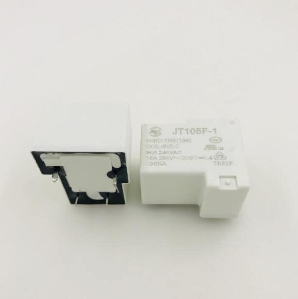
Figure 1: BIRGI JT105F-1-005D-1HS 5VDC Relay. This image shows the compact form factor and pin layout of the relay, highlighting its robust construction suitable for various electrical applications.
4. Setup and Wiring
Before proceeding, ensure all power is disconnected. Refer to the pinout diagram (if available on the product casing) for precise identification of coil and contact terminals. A typical 4-pin power relay like the JT105F-1-005D-1HS usually has two pins for the coil and two pins for the normally open (NO) contact.
- Identify Coil Pins: Locate the two pins designated for the 5VDC coil. These pins will activate the relay when 5VDC is applied across them.
- Connect Control Circuit: Connect your 5VDC control signal (e.g., from a microcontroller or switch) to the coil pins. Ensure correct polarity if the coil is polarized (though most DC relays are not polarity sensitive for the coil, it's good practice to check).
- Identify Contact Pins: Locate the two pins for the load contacts. For a 4-pin relay, these are typically the Common (COM) and Normally Open (NO) contacts.
- Connect Load Circuit: Connect one side of your AC load (e.g., a light, motor) to one of the contact pins (e.g., COM). Connect the other contact pin (e.g., NO) to the AC power source. The other side of your AC load should be connected to the neutral/return path of the AC power source.
- Verify Connections: Double-check all wiring for correctness, security, and proper insulation before restoring power.
Note: If your relay has a Normally Closed (NC) contact in addition to NO, ensure you are connecting to the desired contact type. For this 4-pin model, it is typically a single pole, single throw (SPST) normally open configuration.
5. Operating Instructions
Once properly wired and power is restored, the relay operates as follows:
- De-energized State: When no voltage (or 0V) is applied to the 5VDC coil pins, the relay contacts are in their default state. For a Normally Open (NO) configuration, the contacts are open, and no current flows through the load circuit.
- Energized State: When 5VDC is applied across the coil pins, an electromagnetic field is generated, which pulls the armature and closes the Normally Open (NO) contacts. This completes the load circuit, allowing current to flow and activating the connected AC device.
- Switching Off: Removing the 5VDC from the coil pins de-energizes the coil, causing the armature to return to its default position, opening the NO contacts and deactivating the load.
Ensure the control signal is stable and within the 5VDC specification for reliable operation.
6. Maintenance
The BIRGI JT105F-1-005D-1HS relay is designed for long-term, reliable operation with minimal maintenance. However, periodic checks can help ensure optimal performance and longevity:
- Visual Inspection: Periodically inspect the relay for any signs of physical damage, discoloration, or loose connections.
- Cleanliness: Keep the relay and its surroundings free from dust, dirt, and debris, which can impede heat dissipation or interfere with contact operation.
- Connection Integrity: Ensure all wire connections to the relay terminals remain tight and secure. Loose connections can lead to overheating and intermittent operation.
- Environmental Check: Confirm that the operating environment remains within the specified temperature and humidity ranges.
Note: Do not attempt to open or repair the relay. There are no user-serviceable parts inside.
7. Troubleshooting
If you encounter issues with your BIRGI JT105F-1-005D-1HS relay, consider the following troubleshooting steps:
| Problem | Possible Cause | Solution |
|---|---|---|
| Relay does not click/activate when 5VDC is applied to coil. |
|
|
| Load does not turn ON/OFF when relay activates. |
|
|
| Relay overheats. |
|
|
If problems persist after following these steps, contact customer support or consult a qualified professional.
8. Specifications
| Parameter | Value |
|---|---|
| Model Number | JT105F-1-005D-1HS |
| Brand | BIRGI |
| Coil Voltage | 5VDC |
| Contact Rating | 30A @ 240VAC |
| Number of Pins | 4 |
| Dimensions (Approx.) | 1.18 x 0.79 x 0.39 inches (30 x 20 x 10 mm) |
| Item Weight | 4.3 ounces (122 grams) |
| Type | Power Relay |
9. Warranty and Support
BIRGI products are manufactured to high-quality standards. For specific warranty information, please refer to the documentation provided with your purchase or contact your retailer. If you require technical assistance or have questions regarding the BIRGI JT105F-1-005D-1HS relay, please contact BIRGI customer support through their official website or the contact information provided by your seller.
Please have your model number (JT105F-1-005D-1HS) and purchase details ready when contacting support.