GOLDEN BLUE SZ305
SZ305 Multimeter User Manual
Model: SZ305 | Brand: GOLDEN BLUE
1. Introduction
The GOLDEN BLUE SZ305 Multimeter is a professional 1999 counts smart voltmeter designed for accurate measurement of AC/DC voltage, current, resistance, and capacitance. This versatile tool is suitable for both professionals and DIY enthusiasts, offering smart testing capabilities and a user-friendly design.
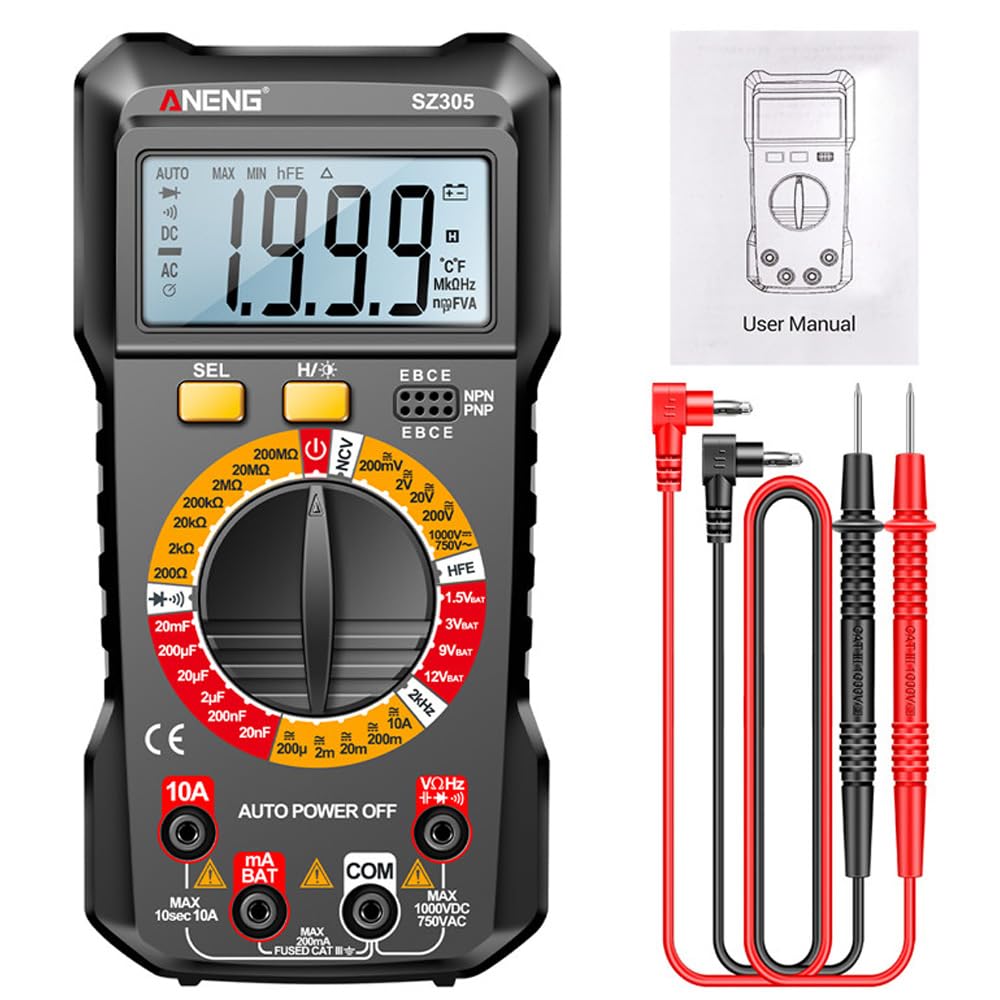
Figure 1.1: SZ305 Multimeter with included accessories.
Key Features:
- Accurate Measurements: 1999 count display for precise readings of AC/DC voltage, current, resistance, and capacitance.
- Smart Functionality: Advanced capabilities for efficient testing of various electrical parameters.
- User-Friendly Design: Intuitive interface, easy-to-read display, and ergonomic controls for enhanced usability.
- Wide Application: Suitable for electronics projects, circuit troubleshooting, and household repairs.
- Durable and Reliable: Constructed with high-quality materials for longevity and dependable performance.
2. Setup
2.1 Battery Installation
The SZ305 Multimeter requires two AAA batteries (not included) for operation. Follow these steps to install the batteries:
- Locate the battery compartment cover on the back of the multimeter.
- Use a screwdriver to open the battery compartment.
- Insert two AAA batteries, ensuring correct polarity (+ and -).
- Replace the battery compartment cover and secure it with the screw.
Note: A low battery indicator will appear on the display when the batteries need replacement.
3. Operating Instructions
3.1 Controls and Display Overview

Figure 3.1: Overview of SZ305 Multimeter controls and display features.
- LCD Display Screen: Shows measurement readings and indicators.
- SEL Button: Used for function switching within a mode (e.g., AC/DC, Diode/Buzzer).
- H/★ Button: Single press for Data Hold (H); Long press for Backlight screen switch (★).
- Rotary Dial: Selects the desired measurement function (e.g., Voltage, Resistance, Current).
- Input Jacks:
- COM Jack: Common (negative) input for all measurements.
- VΩHz Jack: Positive input for Voltage, Resistance, Frequency, Diode, Capacitance, NCV, and Battery tests.
- mA Jack: Positive input for milliampere current measurements.
- 10A Jack: Positive input for 10 Ampere current measurements.
- hFE Triode Jack: For transistor hFE testing.
3.2 LCD Backlight Display
The multimeter features an LCD backlight display for clear visibility in dark environments. To activate the backlight, long press the H/★ button. Long press again to turn it off.

Figure 3.2: The LCD backlight display enhances readability in low-light conditions.
3.3 Automatic Power Off
To conserve battery life, the SZ305 Multimeter is equipped with an automatic power-off feature. If the device is idle for a certain period, it will automatically shut down. Press any button or turn the rotary dial to reactivate it.
3.4 Data Hold Function
To hold the current reading on the display, single press the H/★ button. The "H" indicator will appear on the screen. Press the button again to release the data hold function.
4. Functional Testing
This section details how to perform various measurements using the SZ305 Multimeter.
4.1 Voltage Measurement (AC/DC)
To measure voltage, set the rotary dial to the "V~" (AC voltage) or "V̄-" (DC voltage) gear. Connect the red test lead to the VΩHz jack and the black test lead to the COM jack. Connect the probes across the circuit or component to be measured.

Figure 4.1: Examples of AC voltage, DC voltage, and Hertz frequency measurements.
4.2 Current Measurement (AC/DC)
For current measurement, set the rotary dial to the "A~" (AC current) or "Ā-" (DC current) gear. For currents up to 200uA-10A, connect the red test lead to the 10A jack (or mA jack for smaller currents) and the black test lead to the COM jack. Connect the multimeter in series with the circuit.

Figure 4.2: Examples of hFE Triode, Capacitance, AC current, and DC current measurements.
4.3 Resistance Measurement
Set the rotary dial to the "Ω" gear. Connect the red test lead to the VΩHz jack and the black test lead to the COM jack. Connect the probes across the resistor or component to measure its resistance.
4.4 Capacitance Measurement
Set the rotary dial to the "F" (Capacitance) gear. Connect the red test lead to the VΩHz jack and the black test lead to the COM jack. Connect the probes across the capacitor to measure its capacitance.
4.5 Diode and Buzzer Test
Set the rotary dial to the "Diode/Buzzer" gear. Use the SEL button to switch between diode test and continuity buzzer. For diode test, connect the red probe to the anode and black probe to the cathode. For continuity, touch the probes to the points to be tested; a beep indicates continuity.
4.6 hFE Transistor Test
Set the rotary dial to the "hFE" gear. Insert the transistor leads into the corresponding hFE triode jacks (E, B, C for NPN or PNP). The display will show the hFE value.
4.7 NCV (Non-Contact Voltage) Detection
Set the rotary dial to the "NCV" gear. Move the top of the multimeter near an AC voltage source. The device will beep and the NCV indicator will light up if AC voltage is detected, without direct contact.
4.8 Battery Test (BAT)
Set the rotary dial to the "BAT" gear. Select the desired battery voltage (1.5V, 3V, 9V, 12V) using the SEL button if applicable. Connect the red test lead to the positive terminal and the black test lead to the negative terminal of the battery. The display will show the battery voltage.
Figure 4.3: Examples of battery voltage detection for various battery types.
5. Specifications
The following table outlines the technical specifications and parameters of the GOLDEN BLUE SZ305 Multimeter.

Figure 5.1: Detailed function table for the SZ305 Multimeter.
| Functionality | Range | Resolution | Accuracy |
|---|---|---|---|
| AC Voltage | 200mV-750V | 0.1mV-1V | (1.5%+5d) |
| DC Voltage | 200mV-1000V | 0.1mV-1V | (1.5%+10d) |
| AC Current | 200uA-10A | 0.1uA-10mA | (2.5%+10d) |
| DC Current | 200uA-10A | 0.1uA-10mA | (2.0%+10d) |
| Resistance | 200MΩ | 0.1Ω-100kΩ | (5.0%+10d) |
| Capacitor | 20mF | 0.01nF-10uF | (6.0%+20d) |
| Hz Frequency | 2kHz | 0.1Hz-1Hz | (1.5%+8d) |
| Screen Backlight | Yes | ||
| Data Retention | Yes | ||
| Automatic Power Off | Yes | ||
| Low Battery Indicator | Yes | ||
| Diode Test | Yes | ||
| hFE Transistor | Yes | ||
| Buzzer (Continuity) | Yes | ||
| NCV Voltage | Yes | ||
| BAT Battery Detection | 1.5V/3V/9V/12V | ||
| Maximum Count | 1999 counts | ||
| Material | ABS | ||
| Size | approx. 188x91x38mm / 7.4x3.58x1.5inch | ||
| Battery Type | AAA battery*2 (not included) | ||

Figure 5.2: Physical dimensions of the SZ305 Multimeter.

Figure 5.3: The integrated back support frame allows for tilted placement on a surface.
6. Maintenance
Proper maintenance ensures the longevity and accuracy of your SZ305 Multimeter.
- Cleaning: Wipe the multimeter with a dry, soft cloth. Do not use abrasive cleaners or solvents.
- Storage: Store the device in a cool, dry place away from direct sunlight and extreme temperatures. If storing for extended periods, remove the batteries to prevent leakage.
- Test Leads: Inspect test leads regularly for any signs of damage, such as cracks or frayed insulation. Replace damaged leads immediately.
- Calibration: For professional use, periodic calibration by a qualified technician is recommended to maintain accuracy.
7. Troubleshooting
This section addresses common issues you might encounter with your SZ305 Multimeter.
- No Display / Faint Display:
- Check battery installation and ensure correct polarity.
- Replace batteries if the low battery indicator is on or if the display is faint.
- Incorrect Readings:
- Ensure the rotary dial is set to the correct function for the measurement.
- Verify that test leads are securely connected to the correct input jacks.
- Check test leads for damage or poor contact.
- Ensure the component being tested is properly connected.
- Multimeter Does Not Turn On:
- Confirm batteries are installed and charged.
- Check if the rotary dial is set to an "OFF" position or if the auto-power-off function has activated.
- Buzzer Not Working:
- Ensure the multimeter is in continuity mode (buzzer function).
- Check if the circuit being tested is actually continuous.
If problems persist, contact GOLDEN BLUE customer support for assistance.