Mokernali STC-1000
Mokernali STC-1000 Digital Temperature Controller User Manual
Model: STC-1000
1. Introduction
The Mokernali STC-1000 is a versatile digital temperature controller designed for precise temperature management in various environments. It features both heating and cooling control modes, allowing it to maintain a desired temperature range. This device is suitable for applications such as aquariums, chicken incubators, terrariums, and other temperature-sensitive systems. It operates on an AC 110-220V power supply and supports both Fahrenheit and Celsius temperature displays.

Figure 1.1: The Mokernali STC-1000 Digital Temperature Controller, showing the main unit with its digital display, control buttons, and attached temperature sensor probe.
2. Product Overview
The STC-1000 controller features a clear digital display for current temperature readings and status indicators. It includes intuitive buttons for setting parameters and navigating menus. The device is housed in a durable casing with mounting clips for easy installation.
2.1. Components
- Main Controller Unit: Houses the digital display, control buttons, and internal circuitry.
- Temperature Sensor Probe: An external waterproof NTC sensor for accurate temperature measurement.
- Wiring Terminals: Located on the back for power input, sensor connection, and heating/cooling outputs.
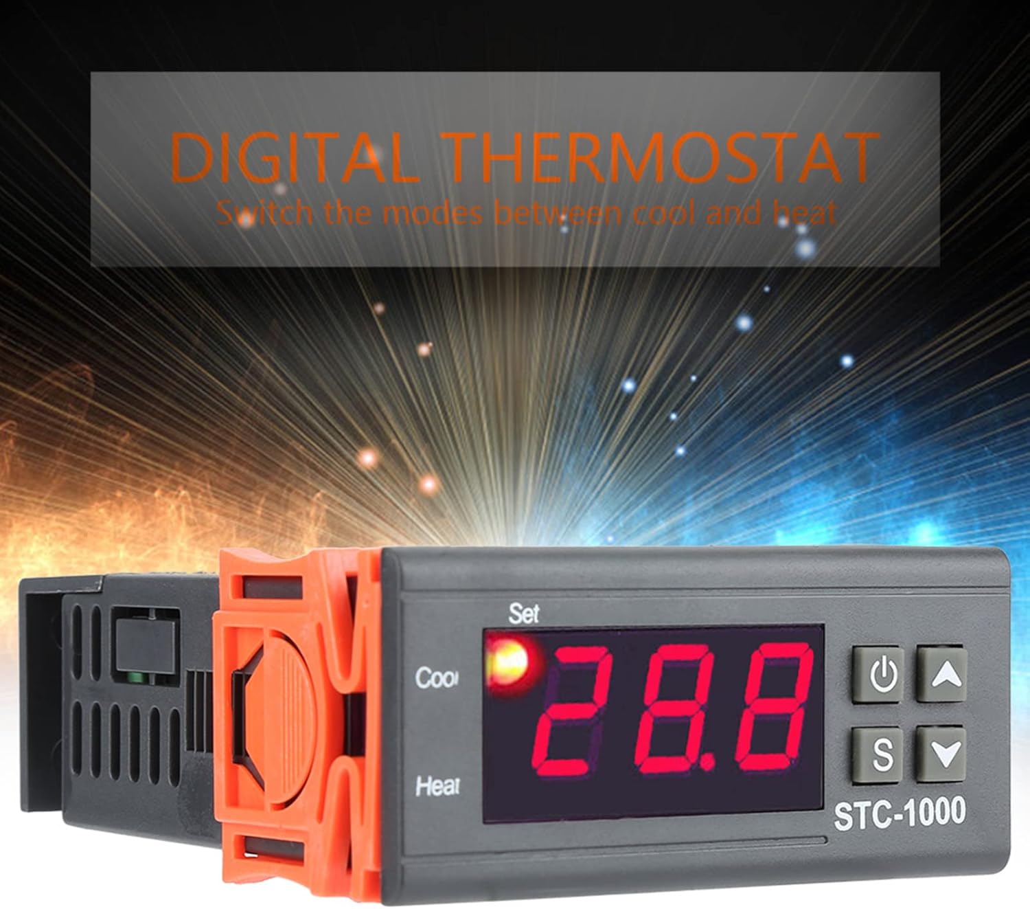
Figure 2.1: Front view of the STC-1000, highlighting the digital display, 'Set' indicator, 'Cool' and 'Heat' indicators, and the control buttons (Power, Set, Up, Down).

Figure 2.2: A detailed view of the STC-1000's digital display and control panel, showing the 'Set' button, 'Up' arrow, 'Down' arrow, and 'Power' button.

Figure 2.3: Close-up image of the waterproof temperature sensor probe, which connects to the controller to measure ambient temperature.
3. Specifications
| Feature | Specification |
|---|---|
| Product Dimensions | 3.15 x 2.76 x 2.36 inches (80 x 70 x 60 mm) |
| Item Weight | 3.87 ounces (0.11 Kilograms) |
| Power Supply | AC 110-220V, 50/60Hz |
| Temperature Control Range | Typically -50°C to 99°C (-58°F to 210°F) - Refer to device display for exact range. |
| Measurement Input | NTC Sensor |
| Output | Relay output for Heating and Cooling |
| Display | Digital LED |
4. Safety Information
Please read and understand all safety instructions before operating the device. Failure to do so may result in electric shock, fire, or damage to the product.
- Ensure the power supply voltage matches the device's requirements (AC 110-220V).
- All wiring should be performed by a qualified individual or with extreme caution, following local electrical codes.
- Do not operate the device in wet or damp conditions unless specifically designed for such environments.
- Keep the sensor and power wires separated to avoid interference.
- Disconnect power before performing any wiring or maintenance.
5. Setup
5.1. Wiring Diagram
The STC-1000 requires careful wiring to ensure proper function and safety. Refer to the diagram below for terminal connections.

Figure 5.1: Wiring diagram for the STC-1000, illustrating connections for power supply, temperature sensor, heating output, and cooling output.
5.2. Terminal Connections
- Terminals 1 & 2: Connect to the AC 110-220V power supply.
- Terminals 3 & 4: Connect the temperature sensor probe. Polarity is typically not critical for NTC sensors.
- Terminals 5 & 6: Connect to the heating device. These terminals act as a relay switch for the heater.
- Terminals 7 & 8: Connect to the cooling device. These terminals act as a relay switch for the cooler.
Note: Strictly distinguish interfaces of relay, sensor, and power. Ensure sensor down-lead and power wire are kept a proper distance to prevent interference.
5.3. Installation
Mount the controller in a dry, well-ventilated area, away from direct heat sources or excessive moisture. Use the integrated mounting clips to secure the unit into a panel cutout. Ensure the temperature sensor is placed in the area where temperature needs to be monitored and controlled, avoiding direct contact with heating or cooling elements unless intended.
6. Operating Instructions
6.1. Power On/Off
Press the Power button (usually marked with ⏻) to turn the device on or off.
6.2. Setting Temperature Parameters
- Set Temperature Value (SV):
Press the S (Set) button once. The current set temperature will flash.
Use the ▲ (Up) and ▼ (Down) buttons to adjust the desired temperature.
Press the S button again or wait a few seconds for the setting to be saved automatically. - Accessing Advanced Settings (P-codes):
Press and hold the S button for approximately 3 seconds to enter the advanced settings menu.
Use the ▲ and ▼ buttons to cycle through the P-codes (P0-P6).
Press S again to view or modify the value of the selected P-code.
Use ▲ and ▼ to change the value.
Press S to confirm the new value and return to the P-code list. Hold Power button or wait to exit the menu.
6.3. Common P-Code Settings
- P0: Heating/Cooling Mode (C/H): Set to 'H' for heating mode (output activates when temperature is below set point) or 'C' for cooling mode (output activates when temperature is above set point).
- P1: Hysteresis/Differential Setting: This value determines the temperature difference between the set point and when the heating/cooling output turns off. For example, if set point is 25°C and hysteresis is 2°C in heating mode, the heater turns on at 23°C and off at 25°C.
- P2: High Temperature Alarm Limit: Sets the maximum allowable temperature.
- P3: Low Temperature Alarm Limit: Sets the minimum allowable temperature.
- P4: Temperature Calibration: Allows for fine-tuning the temperature reading if there's a discrepancy with a known accurate thermometer. Adjust in Celsius or Fahrenheit.
- P5: Delay Start Time (Compressor Delay): Sets a delay before the cooling output activates, useful for protecting compressors.
- P6: High Temperature Alarm (On/Off): Enables or disables the high temperature alarm.
Note: Specific P-code functions and ranges may vary slightly. Always refer to the on-screen indicators and test settings carefully.
7. Maintenance
- Cleaning: Wipe the controller's surface with a soft, dry cloth. Do not use abrasive cleaners or solvents.
- Sensor Care: Ensure the temperature sensor probe is clean and free from debris. Avoid bending or damaging the sensor cable.
- Connections: Periodically check all wiring connections to ensure they are secure and free from corrosion.
8. Troubleshooting
| Problem | Possible Cause | Solution |
|---|---|---|
| Display shows 'LLL' or 'HHH' | Sensor error (open circuit or short circuit) or temperature out of range. | Check sensor connection. Replace sensor if damaged. Ensure temperature is within device's operating range. |
| Display shows 'ERR' | System error or parameter setting error. | Power cycle the device. If error persists, reset to factory settings (refer to advanced settings for reset option, if available). |
| Heating/Cooling not activating | Incorrect mode (P0), incorrect set point, hysteresis too small, wiring issue, or device malfunction. | Verify P0 setting (H for heating, C for cooling). Check set temperature and hysteresis (P1). Inspect wiring to heating/cooling device. Ensure the heating/cooling device itself is functional. |
| Inaccurate temperature reading | Sensor placement, sensor damage, or calibration needed. | Relocate sensor to a representative area. Check sensor for physical damage. Use P4 (Temperature Calibration) to adjust the reading against a known accurate thermometer. |
| Device does not power on | No power supply, incorrect wiring, or internal fault. | Check power source and wiring to terminals 1 & 2. Ensure power button is pressed. |
9. Warranty and Support
Mokernali products are manufactured to high-quality standards. For specific warranty information, please refer to the product packaging or contact your retailer. For technical support or further assistance, please reach out to Mokernali customer service through the contact information provided at the point of purchase or on the official Mokernali website.
Ask a question about this manual
Ask about setup, troubleshooting, compatibility, parts, safety, or missing instructions. Manuals+ will review the question and use this page’s manual context to help answer it.