
1. Introduction and Overview
The Mulcort TOOLTOP ET827 is an innovative 2-in-1 device that ingeniously integrates the functionalities of a digital oscilloscope and a multimeter into a single, portable unit. Designed for DIY enthusiasts and electronic testing professionals, this instrument offers high performance with a 200MSps sampling rate and 40MHz analog bandwidth. Its compact design ensures ease of use and portability, making it an essential tool for various electrical measurements and waveform analysis.

Figure 1: Mulcort TOOLTOP ET827 2in1 Oscilloscope Multimeter. This image displays the front view of the device, highlighting its screen, function buttons, and rotary dial.
2. Key Features
- 2-in-1 Functionality: Combines digital oscilloscope and multimeter functions for versatile testing.
- High Performance: Features a 200Msps real-time sampling rate and 40MHz analog bandwidth.
- Comprehensive Measurement: Supports measurement of DC/AC voltage/current, resistance, capacitance, frequency, temperature, diode/duty ratio, triode, waveform, and continuity.
- Multiple Scanning Modes: Offers Auto, Normal, and Single scanning modes for waveform analysis.
- Data & Waveform Storage: Capable of saving up to 100 sets of data and 50 waveforms for later review.
- TRMS Measurement: Provides accurate virtual value measurements of waveforms, regardless of distortion.
- Safety Protections: Includes overload protection and built-in 500mA/10A fuses for enhanced safety.

Figure 2: 2-in-1 Functionality. This image illustrates the combined multimeter and oscilloscope capabilities, showing examples of capacitance and AC voltage measurements alongside a waveform display.
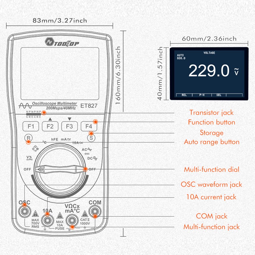
Figure 3: Device Dimensions and Key Components. This diagram provides the physical dimensions of the device and labels important parts such as the transistor jack, function buttons, multi-function dial, and input jacks.
3. Setup
- Unpacking: Carefully remove the ET827 device and all accessories from its packaging. Inspect for any signs of damage.
- Power Source: The device is battery-powered. Ensure appropriate batteries are inserted into the battery compartment, observing correct polarity. (Note: Batteries are not included with the product).
- Initial Power On: Turn the multi-function dial from the "OFF" position to any desired measurement mode (e.g., V~ for AC Voltage) to power on the device.
- Self-Test: The device will perform a brief self-test upon power-on. Wait for the display to stabilize before proceeding with measurements.
4. Operating Instructions
4.1 General Operation
The ET827 features a multi-function dial for selecting measurement modes and dedicated function buttons (F1-F4) for specific operations within each mode. The display provides clear readings and waveform visualizations.
4.2 Oscilloscope Function
To use the oscilloscope function, turn the dial to the "OSC" position. The device will display a waveform. The ET827 supports a 40MHz analog bandwidth and 200Msps sampling rate for accurate waveform capture.
- Automatic Waveform Capture: In waveform mode, press the "R" button (often labeled F1 or a dedicated button) to automatically capture and optimize the waveform display.
- Adjustments: Use the function buttons to adjust parameters such as time base (12.5ns/div ~ 10s/div), vertical amplitude (500mV/div ~ 200V/div), trigger level, and gradient.
- Cursor Measurement: Utilize the cursor function to measure dV (voltage difference), dt (time difference), and 1/dt (frequency).
- Automatic Measurement: The device can automatically measure Vp-p (peak-to-peak voltage), Vavg (average voltage), and Vrms (root mean square voltage).

Figure 4: One-Button Oscilloscope. This image demonstrates the ease of use of the oscilloscope function, showing how pressing the 'R' button automatically captures and displays the waveform.
4.3 Multimeter Function
Rotate the multi-function dial to the desired measurement parameter (e.g., V for voltage, A for current, Ω for resistance, C for capacitance, Hz for frequency, °C for temperature, Diode, hFE for triode, Continuity). Connect the test leads to the appropriate input jacks (VΩCx mA°C, 10A, COM).
- TRMS Measurement: The device supports True RMS measurement, providing accurate readings for non-sinusoidal waveforms.
- REL Function: The REL (Relative) function helps eliminate the influence of lead resistance and distributed capacitance for more precise measurements.
- Auto/Manual Ranging: The device supports both automatic and manual ranging for various measurements.

Figure 5: TRMS and REL Functions. This image highlights the accurate real-time measurement of RMS values and the REL function for eliminating lead resistance and distributed capacitance.

Figure 6: Multimeter Function Overview. This image displays icons representing the various measurement capabilities of the multimeter, including oscilloscope, voltage, current, resistance, capacitance, frequency, temperature, hFE, diode, and continuity.
4.4 Scanning Modes
The oscilloscope function offers three scanning modes:
- Auto Mode: Automatically adjusts the time base and vertical amplitude for a stable waveform display.
- Normal Mode: Displays a waveform only when a trigger condition is met. Useful for capturing specific events.
- Single Mode: Captures and displays a single waveform when the trigger condition is met, then stops. Ideal for non-repetitive signals.
4.5 Data and Waveform Storage
The ET827 allows users to save measurement data and captured waveforms for later analysis.
- Saving Data: The device can store up to 100 sets of measurement data. Refer to the specific button (e.g., 'S' or F4) for saving data in multimeter mode.
- Saving Waveforms: Up to 50 waveforms can be saved in oscilloscope mode. Use the designated save function button.
- Recalling Data/Waveforms: Navigate through the saved data and waveforms using the appropriate menu options or buttons (e.g., 'R' or F1 for recall).
5. Maintenance
- Cleaning: Use a soft, damp cloth to clean the device's exterior. Do not use abrasive cleaners or solvents.
- Storage: When not in use for extended periods, store the device in a cool, dry place, away from direct sunlight and extreme temperatures.
- Battery Care: If the device will not be used for a long time, remove the batteries to prevent leakage and damage.
- Fuse Replacement: The device has built-in 500mA/10A fuses for protection. If a fuse blows, replace it with a fuse of the same type and rating. Refer to the device's internal diagram for fuse location if necessary.
6. Troubleshooting
| Problem | Possible Cause | Solution |
|---|---|---|
| Device does not power on. | Low or dead batteries; Incorrect battery installation; Power switch not fully engaged. | Replace batteries; Check battery polarity; Ensure dial is turned to a measurement mode. |
| No reading or unstable reading in multimeter mode. | Incorrect test lead connection; Blown fuse; Out of measurement range; Poor contact with circuit. | Ensure leads are in correct jacks; Check and replace fuse if necessary; Select appropriate range or use auto-ranging; Ensure good contact. |
| No waveform or distorted waveform in oscilloscope mode. | Incorrect probe connection; Trigger level too high/low; Time base or vertical sensitivity incorrect; Signal too weak/strong. | Check probe connection; Adjust trigger level; Adjust time base and vertical sensitivity; Verify signal source. |
| Data/waveform not saving. | Memory full; Incorrect save procedure. | Delete old data/waveforms; Refer to Section 4.5 for correct saving procedure. |
7. Specifications
| Parameter | Value |
|---|---|
| Analogue Bandwidth | 40MHz |
| Maximum Real-time Sampling Rate | 200Msps |
| Vertical Resolution | 8 bits |
| Number of Channels | 1 |
| Input Resistance | About 10MΩ |
| Ranges of Vertical Sensitivity | 500mV/div ~ 200V/div |
| Ranges of Time Base | 12.5ns/div ~ 10s/div |
| Accuracy of Vertical Amplitude | ±(5%+ 0.2div) |
| Accuracy of Time Base | ±(0.01% + 0.1div) |
| Scanning Modes | Auto/Normal/Single |
| Trigger Level | ± 6 div (0.1div/step) |
| Automatic Measurement Functions | Vp-p, Vavg, Vrms |
| Data Storage Capacity | 100 sets |
| Waveform Storage Capacity | 50 waveforms |
| Item Weight | 0.25 Kilograms (250 g) |
| Model Number | ET827 (MS8230D) |
8. Safety Information
Always observe the following safety precautions when operating the Mulcort TOOLTOP ET827:
- Overload Protection: The device is equipped with overload protection that automatically cuts off power when overloaded.
- Fuses: Built-in 500mA/10A fuses provide dual protection. Do not bypass or use incorrect fuse types.
- Voltage Limits: Do not attempt to measure voltages or currents exceeding the specified maximum ratings of the device.
- Insulation: Ensure your hands are dry and you are properly insulated from ground when making measurements, especially with high voltages.
- Inspection: Before each use, inspect the device and test leads for any damage. Do not use if damaged.
- Professional Use: This device is intended for use by qualified personnel or under their direct supervision.

Figure 7: Safety Features. This image highlights the overload protection and the 500mA, 10A fuses designed to protect both the user and the device.
9. Warranty and Support
For warranty information, technical support, or service inquiries regarding your Mulcort TOOLTOP ET827, please contact the retailer or the manufacturer, Mulcort, directly. Keep your purchase receipt as proof of purchase for any warranty claims.
For further assistance, please refer to the contact information provided with your product packaging or visit the official Mulcort website.