1. Introduction
This manual provides detailed instructions for the installation, configuration, operation, and maintenance of the ASPIRING B75-HM Motherboard. Designed for LGA 1155 Intel processors, this motherboard offers robust performance and a range of connectivity options for various computing needs. Please read this manual thoroughly before proceeding with installation or operation.
2. Product Overview
The ASPIRING B75-HM is a micro-ATX motherboard built with an 8-layer PCB and solid capacitors for enhanced stability and durability. It supports Intel 2nd and 3rd generation Core i3/i5/i7, Pentium, Celeron, and Xeon E3 V1/V2 processors. Key features include:
- LGA 1155 CPU Socket
- 4 x DDR3 DIMM slots supporting up to 32GB dual-channel memory (1066/1333/1600MHz)
- 1 x NVMe M.2 slot (PCIEx4 Gen2 speed)
- 1 x NGFF M.2 Key A&E port for Wi-Fi + Bluetooth modules
- 1 x PCI-E 16X slot and 1 x PCI-E 1X slot
- 1 x SATA3.0 port and 3 x SATA2.0 ports
- Integrated DVI, VGA, and HDMI video output interfaces
- USB 3.0 and USB 2.0 support
- Gigabit Ethernet (Realtek RTL8111F)
- 5.1 Channel HD Audio (Realtek ALC662)
2.1 Component Identification
Refer to the diagram below for the location of key components and connectors on the motherboard.

Figure 1: ASPIRING B75-HM Motherboard Layout. This image displays the various components and connectors on the motherboard, including the CPU socket, RAM slots, PCIe slots, SATA ports, and front panel headers.
2.2 Rear I/O Panel
The rear I/O panel provides external connectivity for peripherals and displays.

Figure 2: Rear I/O Panel. This image shows the PS/2 ports, DVI, VGA, HDMI, USB 2.0, USB 3.0, Ethernet, and audio jacks.
2.3 M.2 Interface
The motherboard features a high-speed NVMe M.2 interface for modern solid-state drives.

Figure 3: NVMe M.2 Interface. This close-up highlights the M.2 slot for high-speed storage devices.
2.4 Front USB 3.0 Header
Connect your case's front panel USB 3.0 ports to this header for high-speed data transfer.

Figure 4: Front USB 3.0 Header. This image shows the internal header for connecting front panel USB 3.0 ports.
3. Setup and Installation
Before installing the motherboard, ensure your system case is compatible with the Micro-ATX form factor. Always handle the motherboard by its edges to avoid static discharge.
3.1 CPU Installation
- Locate the LGA 1155 CPU socket.
- Gently lift the load lever and open the CPU socket cover.
- Align the CPU with the socket, ensuring the golden triangle on the CPU matches the indicator on the socket. Carefully place the CPU into the socket without forcing it.
- Close the socket cover and push the load lever back into place until it clicks.
- Apply thermal paste to the CPU and install the CPU cooler.
3.2 Memory (RAM) Installation
- Locate the four DDR3 DIMM slots.
- Open the clips at both ends of the DIMM slot.
- Align the notch on the DDR3 memory module with the key in the DIMM slot.
- Insert the memory module firmly into the slot until the clips snap into place. For dual-channel operation, refer to your case manual for recommended slot pairing.
3.3 Storage Device Installation (SATA & M.2)
- SATA Drives: Connect SATA data cables from your SSDs/HDDs to the SATA3.0 (1 port) or SATA2.0 (3 ports) connectors on the motherboard. Connect SATA power cables from your power supply to the drives.
- M.2 NVMe SSD: Insert the M.2 NVMe SSD into the M.2 slot at an angle. Push it down and secure it with the provided screw.
3.4 Power Connections
- Connect the 24-pin ATX main power connector from your power supply to the 24-pin ATX power socket on the motherboard.
- Connect the 8-pin ATX 12V CPU power connector from your power supply to the 8-pin CPU power socket near the CPU.
3.5 Front Panel Connections
Connect the power switch, reset switch, power LED, and HDD LED cables from your case to the corresponding pins on the front panel header. Ensure correct polarity for LEDs.
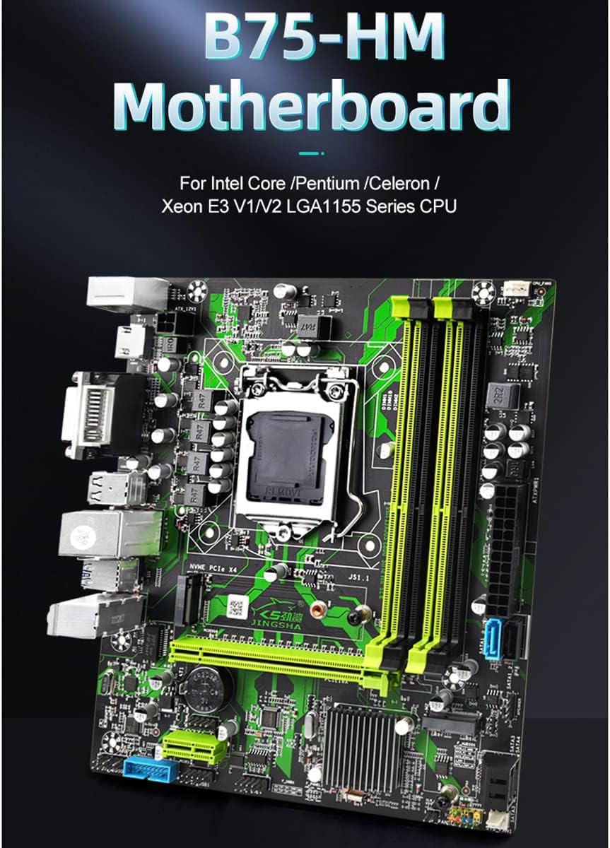
Figure 5: Front Panel Header. This image illustrates the connections for power switch, reset switch, power LED, and HDD LED.
4. Operating Instructions
4.1 First Boot and BIOS Setup
- After completing all hardware installations, connect your monitor, keyboard, and mouse.
- Power on your system. During POST (Power-On Self-Test), press the designated key (usually DEL or F2) to enter the BIOS/UEFI setup utility.
- In the BIOS, configure settings such as boot order, date/time, and enable/disable specific features as needed. Save changes and exit.
4.2 Operating System Installation
Insert your operating system installation media (USB drive or DVD) and follow the on-screen prompts to install your preferred OS. After installation, install all necessary drivers for the motherboard components (chipset, audio, LAN, graphics, etc.) from the manufacturer's website or provided media.
5. Maintenance
Proper maintenance ensures the longevity and optimal performance of your motherboard.
- Dust Removal: Regularly clean dust from the motherboard and components using compressed air. Ensure the system is powered off and unplugged before cleaning.
- BIOS Updates: Check the manufacturer's website periodically for BIOS updates. Only update the BIOS if necessary and follow the instructions carefully to avoid system instability.
- Driver Updates: Keep your drivers updated to ensure compatibility and optimal performance with your operating system and peripherals.
- Physical Inspection: Periodically inspect the motherboard for any signs of damage, loose connections, or bulging capacitors.
6. Troubleshooting
This section addresses common issues you might encounter.
6.1 No Power / No Boot
- Ensure all power cables (24-pin ATX, 8-pin CPU) are securely connected.
- Verify the power supply is switched on and connected to a working outlet.
- Check front panel power switch connection to the motherboard.
- Try a different power supply if available.
6.2 No Display
- Ensure the monitor is connected to the correct video output (onboard DVI/VGA/HDMI or dedicated graphics card).
- Reseat the graphics card (if applicable) and RAM modules.
- Test with a single RAM module in different slots.
- Clear CMOS (refer to motherboard diagram for CLR-CMOS jumper or remove CMOS battery for 5 minutes).
6.3 System Instability / Crashes
- Check CPU and GPU temperatures. Overheating can cause instability.
- Ensure all drivers are correctly installed and up to date.
- Run memory diagnostic tools to check for faulty RAM.
- Verify power supply wattage is sufficient for all components.
7. Specifications
| Feature | Specification |
|---|---|
| Model | B75-HM |
| Form Factor | M-ATX (223.5mm x 195mm) |
| Chipset | Intel Series 7 Chipsets |
| CPU Socket | LGA 1155 |
| Supported Processors | Intel Pentium / Celeron / Core i3/i5/i7 (2nd & 3rd Gen), Xeon E3 V1/V2 |
| Memory Slots | 4 x DDR3 DIMM |
| Memory Type | DDR3 1066/1333/1600MHz |
| Max Memory Capacity | 32GB (Dual Channel Architecture) |
| Graphics Interface | 1 x PCI-E 16X |
| Expansion Slots | 1 x PCI-E 1X, 1 x NVME M.2 (PCIEx4 Gen2), 1 x NGFF M.2 Key A&E (WIFI + Bluetooth) |
| Storage Ports | 1 x SATA3.0, 3 x SATA2.0 |
| USB Ports (Rear) | 4 x USB3.0, 6 x USB2.0 |
| Video Output | 1 x DVI, 1 x VGA, 1 x HDMI |
| LAN | Realtek RTL8111F Gigabit Ethernet |
| Audio | Realtek ALC662 (5.1 Channel) |
| Power Connectors | 1 x 24-pin ATX, 1 x 8-pin ATX 12V |
| Accessories | 1 x I/O Shield, 1 x SATA Cable |
8. Warranty and Support
For warranty information and technical support, please refer to the documentation provided with your purchase or contact your retailer. Keep your proof of purchase for warranty claims.
For further assistance, you may also visit the ASPIRING official website (if available) for updated drivers, FAQs, and support resources.