1. Introduction
This manual provides essential information for the safe installation, operation, and maintenance of the ZIPCOM YCQ1B-63 Automatic Transfer Switch. This device is designed to automatically switch between two power sources, typically a common power supply and a standby power supply, ensuring continuous power availability. It supports both automatic and manual switching modes for operational flexibility.
The YCQ1B-63 series is available in 2-pole (2P), 3-pole (3P), and 4-pole (4P) configurations, with current ratings up to 63A. It features a flame-retardant plastic construction, silver contacts for enhanced conductivity, and multiple protection functions.
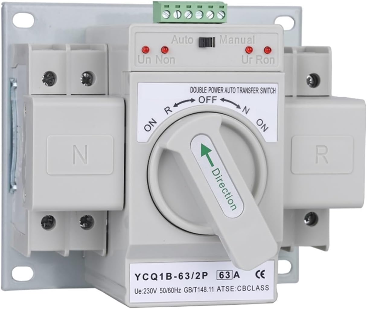
Figure 1.1: Front view of the ZIPCOM YCQ1B-63 Automatic Transfer Switch, showing the auto/manual selector and power indicators.
2. Safety Information
WARNING: Installation and maintenance of this device should only be performed by qualified electricians in accordance with all local and national electrical codes. Failure to follow these instructions may result in electric shock, fire, or serious injury.
- Always disconnect all power sources before installing or servicing the transfer switch.
- Ensure proper grounding of the device.
- Verify voltage and current ratings match your electrical system requirements.
- Do not operate the switch if it appears damaged.
- Keep children and unauthorized personnel away from electrical installations.
3. Product Features
- Automatic and Manual Switching: Allows for flexible operation between automatic power transfer and manual control.
- Flame-Retardant Material: Constructed from flame-retardant plastic for enhanced safety, good insulation, and high temperature resistance.
- Robust Contacts: Features silver contacts for both motion and static electricity, significantly improving conductivity and product lifespan.
- Comprehensive Protection: Supports multiple protection functions including short circuit, overload, phase loss, and undervoltage protection.
- Signal Output Port: Includes a built-in standing open signal output port for connection with signal indicators.
- Quick Conversion: Ensures a rapid power conversion time of approximately 2 seconds.
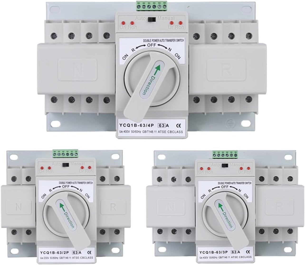
Figure 3.1: Overview of the YCQ1B-63 series, showing 2-pole, 3-pole, and 4-pole configurations.
4. Installation and Setup
Professional installation is highly recommended for this device. Ensure that the installation environment is dry, well-ventilated, and free from corrosive gases or excessive dust. Mount the transfer switch securely to a stable surface.
4.1 Wiring Connections
Refer to the wiring diagrams provided on the device and consult a qualified electrician for proper connection. The device is designed to connect two independent power sources (common power supply and standby power supply) to a single load.

Figure 4.1: Side view of the 2-pole (2P) model, illustrating the terminal block for control wiring and main power connections. The label provides electrical instructions for common and backup power sources.

Figure 4.2: Side view of the 4-pole (4P) model, showing the terminal block for control wiring and main power connections. The label provides electrical instructions for common and backup power sources, including neutral connections.
Key Connection Points:
- Common Power Supply (Normal): Connect to the primary power source.
- Standby Power Supply (Backup): Connect to the secondary power source (e.g., generator, UPS).
- Load: Connect to the electrical panel or devices requiring power.
- Control Terminals (1-6): Used for signal indicators and potentially external control, as detailed on the device label.
5. Operating Instructions
The ZIPCOM YCQ1B-63 Automatic Transfer Switch offers both automatic and manual operation modes.
5.1 Automatic Mode
In automatic mode, the switch continuously monitors the common power supply. If the common power supply fails or experiences an abnormality (e.g., undervoltage, phase loss), the switch will automatically transfer the load to the standby power supply within approximately 2 seconds. Once the common power supply is restored and stable, the switch will automatically transfer the load back to the common power supply.
- Set the selector switch on the front panel to the "Auto" position.
- The device will monitor both power sources and perform transfers as needed.
- Indicator lights (Un, Non, Ur, Ron) will show the status of the power sources and the switch position.
5.2 Manual Mode
For situations where automatic switching is not desired, the device can be operated manually. This allows for direct control over which power source is connected to the load.
- Set the selector switch on the front panel to the "Manual" position.
- Use the main rotary handle to select between the "ON R" (Common Power), "OFF", and "ON N" (Standby Power) positions.
- Ensure the handle is fully engaged in the desired position.
6. Maintenance
The ZIPCOM YCQ1B-63 Automatic Transfer Switch is designed for reliable operation with minimal maintenance. However, periodic inspection is recommended to ensure optimal performance and safety.
- Visual Inspection: Regularly check for any signs of physical damage, loose connections, or discoloration due to overheating.
- Cleaning: Keep the device free from dust and debris. Use a dry, soft cloth for cleaning. Do not use liquid cleaners.
- Terminal Tightness: Periodically verify that all terminal connections are secure.
- Functionality Test: If safe to do so, periodically test the automatic transfer function by simulating a power outage on the common supply.
Any maintenance or repairs beyond simple cleaning and inspection should be performed by a qualified technician.
7. Troubleshooting
If you encounter issues with your ZIPCOM YCQ1B-63 Automatic Transfer Switch, consider the following common problems and solutions:
- No Power Transfer:
- Check if both common and standby power sources are active and within voltage specifications.
- Ensure the switch is set to "Auto" mode for automatic transfer.
- Verify all wiring connections are secure and correct.
- Indicator Lights Not Functioning:
- Confirm power is supplied to the device.
- Inspect for loose control wiring connections.
- Overload/Short Circuit Tripping:
- Identify and resolve the cause of the overload or short circuit in the connected load.
- Ensure the device's current rating (63A) is appropriate for your application.
For persistent issues or complex problems, contact a qualified electrician or ZIPCOM customer support for assistance.
8. Specifications
| Feature | Specification |
|---|---|
| Model Series | YCQ1B-63 (2P, 3P, 4P) |
| Working Frequency | 50Hz / 60Hz |
| Rated Voltage | AC 400V |
| Operating Voltage | AC 220V |
| Current Specifications | 10A - 63A |
| Standards Compliant | IEC60947-6-1 |
| Operation Method | Automatic and Manual |
| ATS Level | CB |
| Conversion Time | < 2 seconds |
| Conversion Method | Self-return |
| Contact Material | Silver |
| Enclosure Material | Flame-retardant Plastic |
| Item Weight | Approximately 2.2 pounds (1 kg) |
Note: Specifications are subject to change without notice.
9. Warranty and Support
For warranty information, technical support, or service inquiries, please contact your point of purchase or refer to the official ZIPCOM website. Keep your purchase receipt as proof of purchase.
Manufacturer: ZIPCOM
For further assistance, please visit: ZIPCOM on Amazon