1. Introduction
The Cyeelves Digital Multimeter VC830L is a versatile instrument designed for accurate and precise electrical measurements. It is an essential tool for troubleshooting, maintenance, and repair tasks across various applications, including automotive systems, household appliances, and scientific experiments.
This multimeter measures AC and DC voltage, DC current, resistance, capacitance, and frequency. It also includes functions such as diode testing, continuity testing with audible alerts, and data holding for convenient result retention.
Package Contents:
- Cyeelves Digital Multimeter (VC830L)
- One pair of Digital Multimeter Test Leads
- One 9V Battery (pre-installed)
- Instruction Manual (this document)

Image 1.1: The Cyeelves Digital Multimeter VC830L is suitable for a wide range of applications, including electrical repair, factory testing, and engineering tasks.
2. Safety Information
Safety is paramount when working with electrical equipment. Always adhere to the following safety guidelines to prevent personal injury or damage to the multimeter.
- Overload Protection: The multimeter features built-in explosion-proof ceramic fuse tubes and overload protection to safeguard the device and user from excessive voltage spikes.
- Silicone Cover: The protective silicone cover helps prevent damage from drops and provides insulation against electric shocks.
- Inspect Before Use: Before each use, inspect the multimeter and test leads for any signs of damage, cracks, or exposed wiring. Do not use if damaged.
- Voltage Limits: Do not exceed the maximum input limits for each measurement range. The maximum operating voltage is 600V DC.
- Proper Connection: Always connect the test leads to the correct input jacks for the desired measurement.
- De-energize Circuits: Whenever possible, de-energize the circuit under test before making connections.
- Avoid Wet Conditions: Do not operate the multimeter in wet or damp environments.
- Professional Use: If you are unfamiliar with electrical testing, seek guidance from a qualified professional.
3. Product Overview
Familiarize yourself with the components of your Cyeelves Digital Multimeter VC830L.
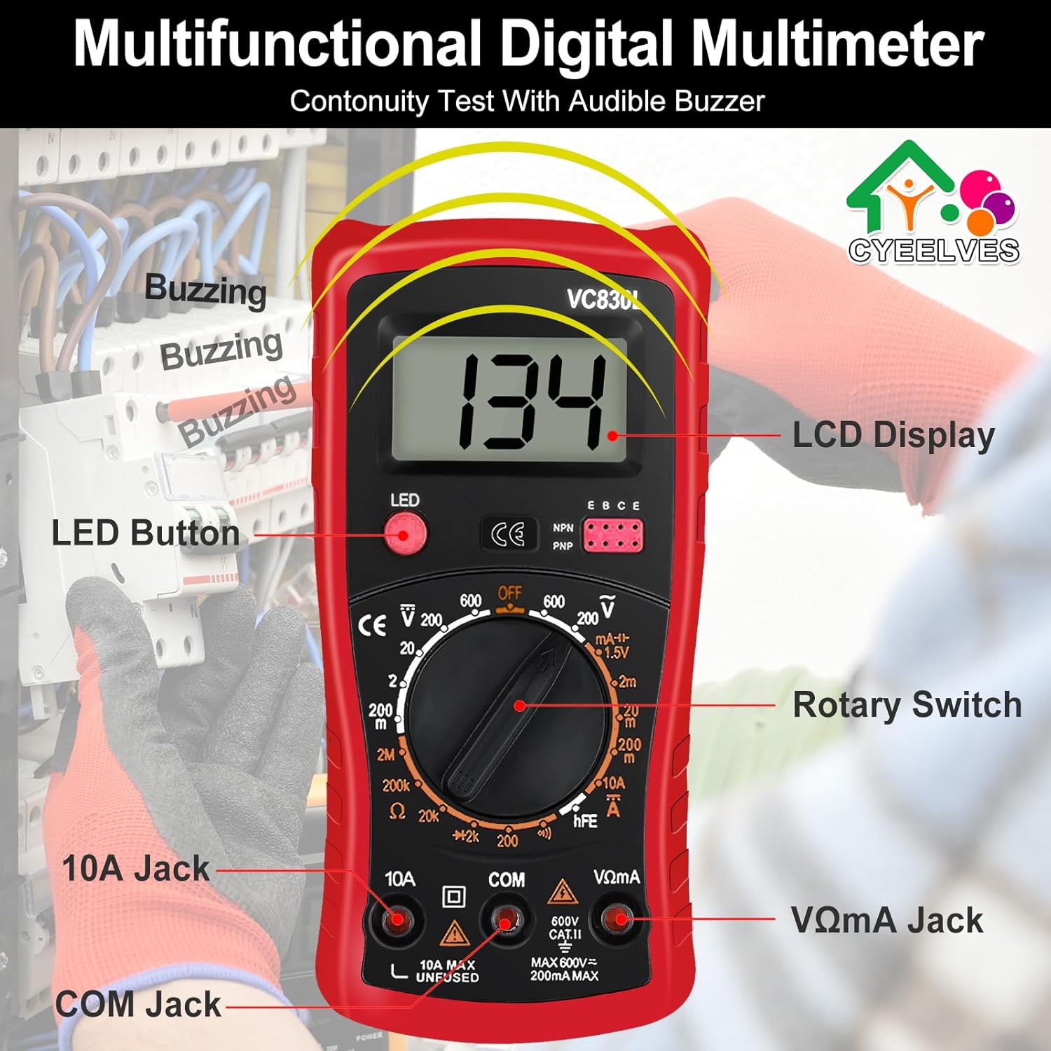
Image 3.1: Front view of the multimeter with key components labeled, including the LCD Display, LED Button, Rotary Switch, 10A Jack, COM Jack, and VΩmA Jack.
- LCD Display: Large screen for clear digital readings, even in low-light conditions with backlight.
- LED Button: Activates the display backlight.
- Rotary Switch: Used to select the desired measurement function and range.
- 10A Jack: Input for measuring high DC current (up to 10A).
- COM Jack: Common (negative) input for all measurements.
- VΩmA Jack: Input for measuring voltage, resistance, capacitance, frequency, diode, continuity, and low DC current.
- Folding Support: A foldable bracket on the back allows for hands-free operation.
- Non-slip Grip: Ergonomic design for secure handling.

Image 3.2: Side and back views illustrating the multimeter's dimensions, non-slip grip, and the adjustable folding support for convenient hands-free use.
4. Setup and Initial Use
Your multimeter comes with a 9V battery pre-installed. Follow these steps for initial setup.
4.1. Connecting Test Leads
- Insert the black test lead into the COM (Common) jack.
- For most measurements (voltage, resistance, capacitance, frequency, diode, continuity, and low current), insert the red test lead into the VΩmA jack.
- For high current measurements (up to 10A DC), insert the red test lead into the 10A jack. Ensure the rotary switch is set to the appropriate 10A range.
4.2. Powering On/Off and Backlight
- To power on the multimeter, rotate the switch from the "OFF" position to any desired measurement function.
- To activate the LCD backlight, press the LED button. Press it again to turn off the backlight.
- To power off the multimeter, rotate the switch back to the "OFF" position.
5. Operating Instructions
This section details how to perform various measurements with your multimeter.
5.1. Measuring DC Voltage (V—)
- Insert the black test lead into the COM jack and the red test lead into the VΩmA jack.
- Rotate the switch to the desired "V—" (DC Voltage) range. Start with the highest range if the voltage is unknown.
- Connect the test probes in parallel across the component or circuit to be measured. The red probe to the positive side, black to the negative.
- Read the voltage value on the LCD display.
5.2. Measuring AC Voltage (V∼)
- Insert the black test lead into the COM jack and the red test lead into the VΩmA jack.
- Rotate the switch to the desired "V∼" (AC Voltage) range. Start with the highest range if the voltage is unknown.
- Connect the test probes in parallel across the AC source or component.
- Read the voltage value on the LCD display.

Image 5.1: Demonstrations of measuring DC voltage from a 9V battery and AC voltage from a standard wall outlet using the multimeter.
5.3. Measuring DC Current (A—)
Caution: Always connect the multimeter in series with the circuit when measuring current. Never connect it in parallel across a voltage source, as this can damage the multimeter and the circuit.
- For low current (mA): Insert the black test lead into the COM jack and the red test lead into the VΩmA jack.
- For high current (10A): Insert the black test lead into the COM jack and the red test lead into the 10A jack.
- Rotate the switch to the appropriate "A—" (DC Current) range (e.g., 200mA, 10A).
- Open the circuit where you want to measure current. Connect the multimeter in series, ensuring the current flows through the multimeter.
- Read the current value on the LCD display.
5.4. Measuring Resistance (Ω)
Caution: Ensure the circuit or component is completely de-energized before measuring resistance. Measuring resistance on a live circuit can damage the multimeter.
- Insert the black test lead into the COM jack and the red test lead into the VΩmA jack.
- Rotate the switch to the "Ω" (Resistance) range. Start with a higher range if the resistance is unknown.
- Connect the test probes across the component whose resistance you want to measure.
- Read the resistance value on the LCD display.
5.5. Continuity Test (♫)
The continuity test checks for a complete electrical path between two points. An audible buzzer will sound if continuity is detected.
- Insert the black test lead into the COM jack and the red test lead into the VΩmA jack.
- Rotate the switch to the continuity (♫) position.
- Touch the test probes to the two points you want to check for continuity.
- If a continuous path exists (low resistance), the buzzer will sound, and the display will show a low resistance value. If no continuity, the display will show "OL" (Open Line).
5.6. Diode Test (→|—)
The diode test measures the forward voltage drop of a diode.
- Insert the black test lead into the COM jack and the red test lead into the VΩmA jack.
- Rotate the switch to the diode (→|—) position.
- Connect the red probe to the anode and the black probe to the cathode of the diode. The display will show the forward voltage drop (typically 0.5V to 0.8V for silicon diodes).
- Reverse the probes. The display should show "OL" (Open Line) for a good diode. If it shows a reading in both directions or "OL" in both directions, the diode is likely faulty.
5.7. Data Hold Function
To freeze the current reading on the display, press the "HOLD" button (if available, or indicated by the LED button if it has dual functionality). Press it again to release the hold function.
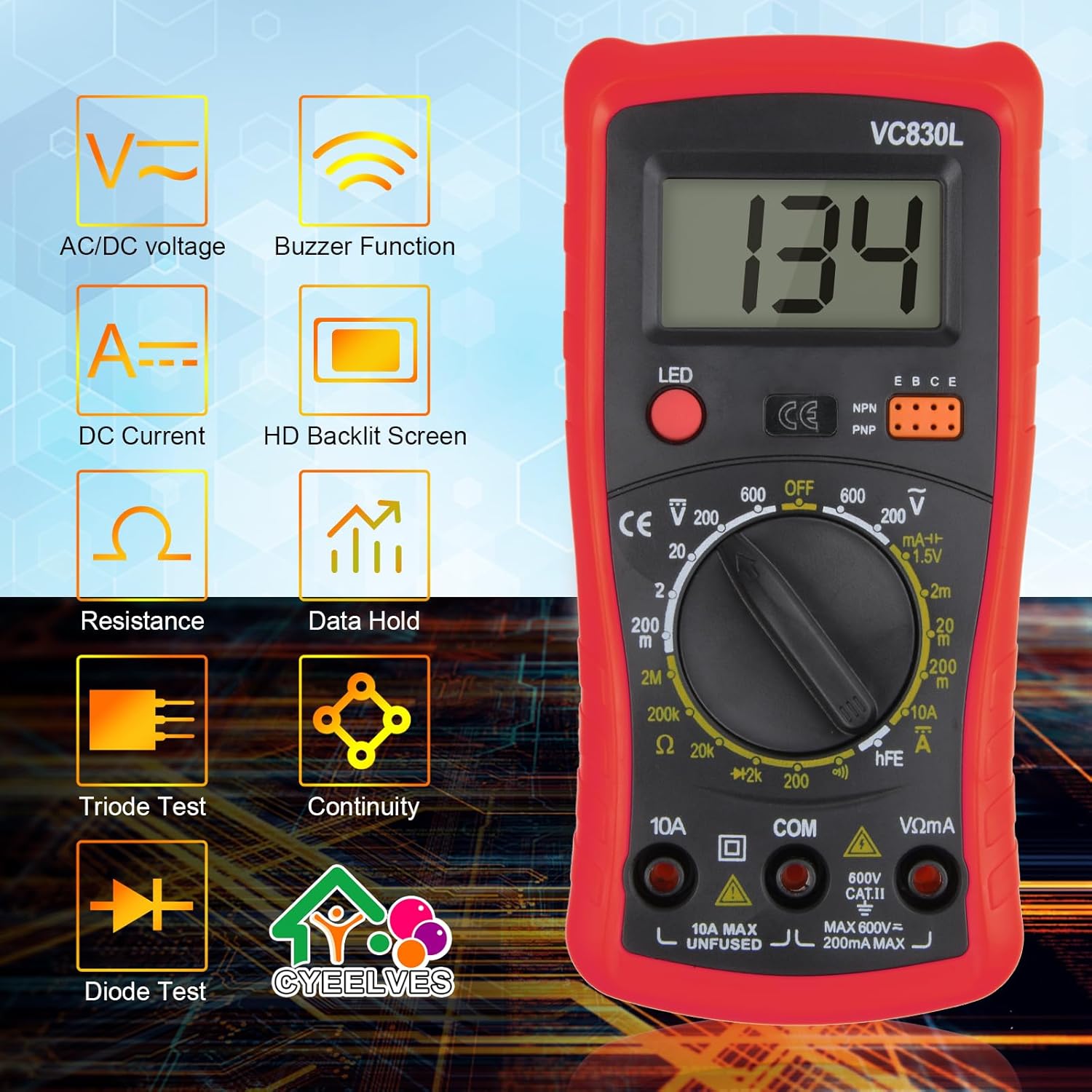
Image 5.2: Visual representation of the various functions available on the Cyeelves Digital Multimeter VC830L.
6. Maintenance
Proper maintenance ensures the longevity and accuracy of your multimeter.
6.1. Cleaning
- Wipe the casing with a damp cloth and mild detergent. Do not use abrasives or solvents.
- Ensure the multimeter is powered off and test leads are disconnected before cleaning.
6.2. Battery Replacement
When the battery indicator appears on the LCD, the 9V battery needs to be replaced.
- Ensure the multimeter is powered off and all test leads are disconnected.
- Locate the battery compartment cover on the back of the multimeter.
- Unscrew the retaining screw(s) and remove the cover.
- Carefully remove the old 9V battery and replace it with a new one, observing polarity.
- Replace the battery compartment cover and secure it with the screw(s).
6.3. Fuse Replacement
If the current measurement function stops working, the fuse may need replacement. Refer to the specifications for the correct fuse type.
- Ensure the multimeter is powered off and all test leads are disconnected.
- Open the multimeter casing (this may require removing the silicone cover and screws).
- Locate the blown fuse (typically near the current input jacks).
- Replace the fuse with one of the identical type and rating (e.g., 10A/250V fast-blow fuse for the 10A range, 200mA/250V for the mA range).
- Carefully reassemble the multimeter, ensuring all screws are tightened and the silicone cover is properly fitted.
6.4. Storage
- Store the multimeter in a cool, dry place, away from direct sunlight and extreme temperatures.
- If storing for extended periods, remove the battery to prevent leakage.
7. Troubleshooting
If you encounter issues with your multimeter, refer to the following common problems and solutions.
| Problem | Possible Cause | Solution |
|---|---|---|
| No display or dim display | Dead or low battery; Multimeter is off. | Replace the 9V battery; Turn the rotary switch to an ON position. |
| "OL" (Overload) displayed | Measurement exceeds selected range; Open circuit (for continuity/resistance). | Select a higher range; Check for breaks in the circuit or component. |
| Incorrect readings | Incorrect function/range selected; Poor test lead connection; Faulty test leads. | Verify function and range; Ensure leads are firmly inserted; Inspect and replace leads if damaged. |
| Current measurement not working | Blown fuse; Incorrect jack used (e.g., VΩmA for 10A). | Replace the fuse (see Section 6.3); Ensure red lead is in the correct current jack (10A or VΩmA). |
| No continuity buzzer | Open circuit; Multimeter not in continuity mode. | Check the circuit for breaks; Ensure rotary switch is set to continuity (♫). |
8. Specifications
Technical specifications for the Cyeelves Digital Multimeter VC830L.
| Feature | Detail |
|---|---|
| Model Number | VC830L |
| Display | LCD with Backlight |
| DC Voltage Range | 200mV - 600V |
| AC Voltage Range | 200V - 600V |
| DC Current Range | 200µA - 10A |
| Resistance Range | 200Ω - 2MΩ |
| Continuity Test | Yes, with Buzzer |
| Diode Test | Yes |
| Power Source | 9V Battery (NEDA 1604 or 6F22 type) |
| Dimensions (L x W x H) | 13.5 x 6.9 x 3 cm (5.3 x 2.7 x 1.2 inches) |
| Weight | 226 g (approx.) |
| Material | High-quality ABS plastic and silicone |
| Safety Standard | IEC 61010-1:2000-1 |
9. Warranty and Support
Cyeelves products are designed for reliability and performance. While specific warranty details are not provided in this manual, please retain your proof of purchase for any warranty claims.
For technical support, troubleshooting assistance, or inquiries regarding your Cyeelves Digital Multimeter VC830L, please contact Cyeelves customer service through the retailer where the product was purchased or visit the official Cyeelves website for contact information.
Always refer to the latest information available from the manufacturer for the most up-to-date support and warranty policies.
