1. Introduction
This manual provides detailed instructions for the installation, operation, and maintenance of your Elprico H310 LGA 1151 Micro ATX DDR4 Motherboard. Please read this manual thoroughly before proceeding with installation to ensure proper setup and optimal performance.
2. Safety Information
- Always disconnect the power supply from the wall outlet before installing or removing any components.
- Wear an anti-static wrist strap to prevent electrostatic discharge (ESD) damage to components.
- Handle components by their edges to avoid touching sensitive parts.
- Ensure proper ventilation in your PC case to prevent overheating.
- Keep the motherboard away from moisture and extreme temperatures.
3. Product Overview
The Elprico H310 LGA 1151 Micro ATX DDR4 Motherboard is designed for desktop computers, supporting Intel 8th and 9th Generation Core processors. It features a stable power supply, high-speed H310 chipset, and rich expansion ports for versatile computing tasks.
Key Features:
- Wide CPU Compatibility: Supports LGA 1151 socket for Intel 8th and 9th Generation Core processors.
- Dual-Channel DDR4 Memory: Two DDR4 DIMM slots supporting up to 32GB of RAM with effective frequencies of 1066/1333/1600 MHz.
- Stable Power Supply: Features a three-phase power design with all solid-state capacitors and 24+8 pin power connectors for reliable operation.
- High-Speed Chipset: Utilizes the Intel H310 chipset for stable and reliable performance.
- Integrated Graphics: Equipped with an integrated graphics processor and multiple display outputs (DVI, HDMI compatible, VGA).
- Rich Expansion Ports: Includes SATA 6Gb/s ports, NVME M.2 slot, PCIe X16 slot, PCIe X1 slot, USB 3.0/2.0, PS/2, RJ45 1000Mbps, and audio ports.
Motherboard Layout:
Below are images illustrating the various components and ports on the motherboard.

Figure 3.1: Top-down view of the motherboard, showing the LGA 1151 CPU socket and the Intel H310 chipset area.
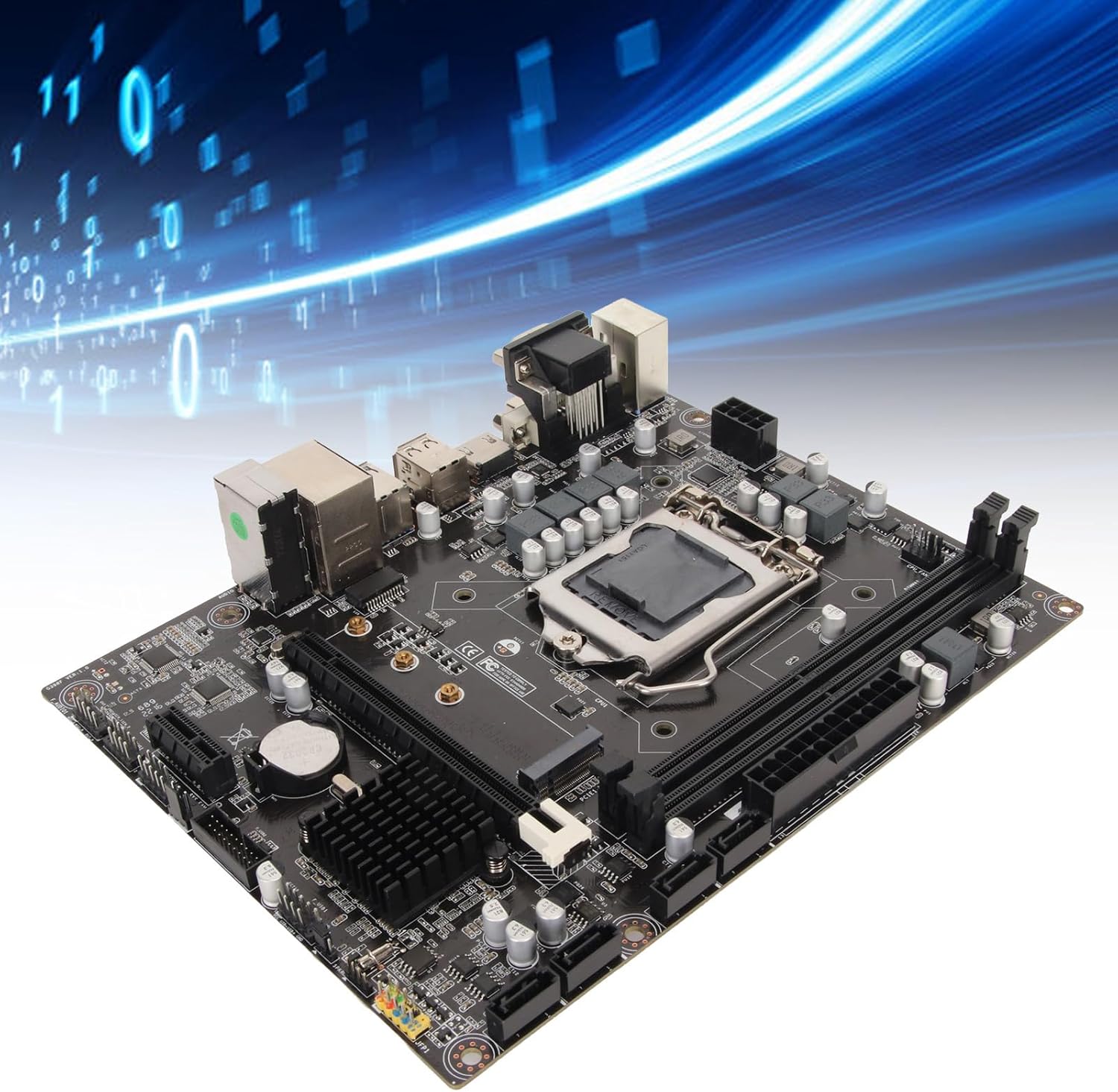
Figure 3.2: Component diagram highlighting the CPU socket, DDR4 memory slots, H310 chipset, and SATA 3.0 (6Gb/s) ports.
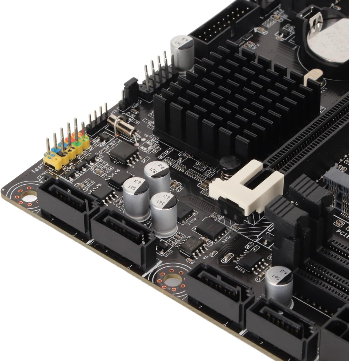
Figure 3.3: Detailed view of the rear I/O panel, featuring DVI, HDMI, VGA, USB 2.0/3.0, LAN, and audio jacks.
4. Installation Guide (Setup)
Follow these steps carefully to install your motherboard and its components.
4.1 CPU Installation
- Locate the LGA 1151 CPU socket on the motherboard.
- Gently push down the load lever and pull it sideways to open the CPU socket cover.
- Align the triangular mark on your Intel LGA 1151 processor with the corresponding mark on the socket.
- Carefully place the CPU into the socket without forcing it.
- Close the socket cover and push the load lever back into place until it clicks.

Figure 4.1: CPU socket area, showing the mechanism for processor installation.
4.2 RAM Installation
- Locate the two DDR4 DIMM slots.
- Open the clips at both ends of the memory slot.
- Align the notch on the DDR4 memory module with the key in the DIMM slot.
- Insert the memory module firmly into the slot until the clips snap into place.
4.3 Storage Installation
The motherboard supports both SATA and NVMe M.2 storage devices.
SATA Drives:
- Connect one end of a SATA data cable to a SATA 6Gb/s port on the motherboard.
- Connect the other end of the SATA data cable to your SATA HDD/SSD.
- Connect a SATA power cable from your power supply to the SATA HDD/SSD.
NVMe M.2 SSD:
- Locate the M.2 slot on the motherboard.
- Remove the M.2 standoff screw.
- Insert the NVMe M.2 SSD into the slot at a 30-degree angle.
- Gently push down the SSD and secure it with the M.2 standoff screw.
4.4 Expansion Card Installation (PCIe)
- Locate the PCIe X16 or PCIe X1 slots.
- Remove the corresponding expansion slot cover from your PC case.
- Align your expansion card (e.g., graphics card) with the chosen PCIe slot.
- Press down firmly until the card is fully seated in the slot.
- Secure the card to the case with a screw.
4.5 Power Connections
- Connect the 24-pin ATX power connector from your power supply to the main 24-pin power socket on the motherboard.
- Connect the 8-pin ATX 12V power connector from your power supply to the 8-pin power socket near the CPU.
4.6 Front Panel Connections
Connect the cables from your PC case's front panel (USB, audio, power button, reset button, LED indicators) to the corresponding headers on the motherboard. Refer to the motherboard diagram for exact header locations.
4.7 Mounting the Motherboard
- Install standoffs in your PC case according to the Micro ATX form factor.
- Carefully place the motherboard onto the standoffs, ensuring the rear I/O ports align with the case's I/O shield.
- Secure the motherboard with screws.

Figure 4.2: General view of the motherboard, illustrating its Micro ATX form factor and component placement.
5. Operating Instructions
5.1 First Boot
After completing all hardware installations, connect your monitor, keyboard, and mouse. Power on your system. The system should display the BIOS/UEFI splash screen.
5.2 BIOS/UEFI Setup
To enter the BIOS/UEFI setup utility, press the DEL or F2 key repeatedly during the initial boot sequence. Here you can configure boot order, system time, and other advanced settings.
5.3 Driver Installation
After installing your operating system, install the necessary drivers for the chipset, integrated graphics, LAN, and audio. These drivers are typically provided on a support CD or can be downloaded from the manufacturer's website.
6. Maintenance
6.1 Cleaning
Regularly clean your PC case and motherboard to prevent dust buildup, which can lead to overheating. Use compressed air to remove dust from fans, heatsinks, and other components. Ensure the system is powered off and unplugged before cleaning.
6.2 BIOS Updates
Periodically check the manufacturer's website for BIOS/UEFI updates. Updates can improve system stability, add support for new hardware, or fix bugs. Follow the provided instructions carefully when updating the BIOS to avoid system damage.
7. Troubleshooting
7.1 Common Issues
- No Power: Check all power connections (24-pin, 8-pin CPU, GPU, SATA) and ensure the power supply is switched on.
- No Display: Verify monitor connection, ensure graphics card (if dedicated) is properly seated and powered, and try reseating RAM modules.
- System Instability/Crashes: Check CPU and GPU temperatures, ensure RAM is correctly installed, and verify driver versions.
- Boot Device Not Found: Check SATA/M.2 connections, verify boot order in BIOS/UEFI, and ensure the operating system is properly installed on the drive.
7.2 Error Codes
If your motherboard has a diagnostic LED display or emits beep codes, consult the motherboard's specific documentation (if available) for the meaning of these codes. Common beep codes often indicate issues with RAM, CPU, or graphics.
8. Specifications
| Feature | Specification |
|---|---|
| Brand | Elprico |
| Model Name | Elpricop91byt60k7 |
| CPU Socket | LGA 1151 |
| Compatible Processors | Intel 8th Generation, 9th Generation Core Processors |
| Chipset Type | Intel H310 |
| RAM Memory Technology | DDR4 |
| Memory Slots | 2 (Dual-Channel) |
| Maximum RAM Size | 32 GB |
| Memory Clock Speed | 1600 MHz (Effective) |
| Compatible Devices | Desktop Computer |
| Total USB Ports | 14 (Various types, including USB 3.0/2.0) |
| Form Factor | Micro ATX (Approx. 21.5 x 17 cm / 8.5 x 6.7 inches) |
| Integrated Battery | CR2032 (240 mAh) |
9. Warranty and Support
9.1 Manufacturer Warranty
This product comes with a 1 Year Warranty Against Manufacturer Defects. Please retain your proof of purchase for warranty claims. For specific terms and conditions, refer to the warranty information provided at the time of purchase or contact the seller.
9.2 Technical Support
For technical assistance, troubleshooting, or further inquiries, please contact your retailer or the manufacturer's support channels. Information regarding spare parts availability and software updates is currently unavailable.