1. Introduction
This user manual provides essential information for the safe and effective operation of your BOSYTRO Adjustable Switching Power Supply, Model ST-24V600W. This device is designed to convert AC input voltage (110V/220V) to a stable, adjustable DC output ranging from 0-24V and 0-25A, with a maximum power output of 600W. Please read this manual thoroughly before installation and use to ensure optimal performance and safety.
2. Safety Instructions
Always adhere to the following safety precautions to prevent electric shock, fire, or damage to the unit and connected devices.
- Electrical Safety: Ensure the power supply is properly grounded. Do not operate in wet or damp conditions. Disconnect power before making any connections or adjustments.
- Voltage Selection: Verify the AC input voltage switch (110V/220V) is set correctly for your region's power supply before connecting to mains. Incorrect setting can cause severe damage.
- Ventilation: Ensure adequate airflow around the unit. Do not block ventilation holes. The built-in cooling fan will activate when the unit reaches a certain temperature to maintain optimal operating conditions.
- Overload Protection: Do not exceed the maximum output current or power rating. The unit features intelligent protection against overload, over-voltage, short-circuit, and over-temperature.
- Professional Installation: Installation and wiring should be performed by qualified personnel, especially for AC input connections.
3. Product Overview
The BOSYTRO ST-24V600W power supply features a robust design with an aluminum shell and an integrated LED digital display for real-time voltage and current monitoring.

Figure 3.1: Overall view of the BOSYTRO power supply, showcasing its compact design and the included wiring terminals.
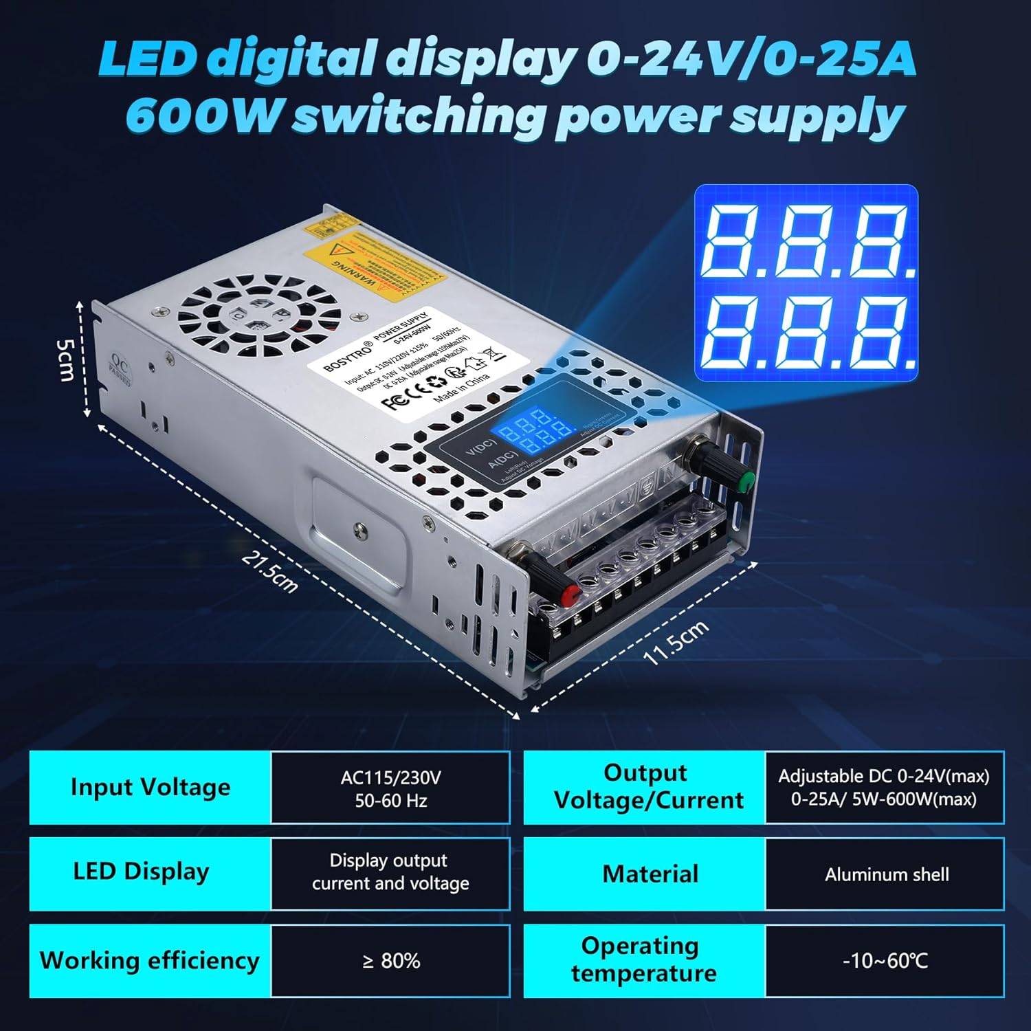
Figure 3.2: Product dimensions (21.5cm x 11.5cm x 5cm) and key specifications, including adjustable output voltage/current and LED display.

Figure 3.3: Depiction of the efficient heat dissipation system, featuring a built-in cooling fan and multiple ventilation holes to extend service life.

Figure 3.4: Wiring port diagram and location of the adjustable voltage and current knobs for precise output control.

Figure 3.5: Overview of the power supply's multiple protection functions: short circuit, over-voltage, overload, earth leakage, overcurrent, and overheat protection.

Figure 3.6: Internal component layout, highlighting the fan cooling device, aluminum housing, adjustable voltage knob, LED digital display, built-in filter jammers, and high-quality PCB circuit board.

Figure 3.7: Diverse applications for the power supply, including LED lighting, advertising displays, CCTV, medical equipment, car audio, and automation.
4. Setup
Follow these steps for proper installation and setup of your power supply.
- Unpacking: Carefully remove the power supply from its packaging. Inspect for any visible damage.
- Voltage Selection: Locate the AC input voltage selector switch (usually a small red switch) on the side of the unit. Set it to either 110V or 220V according to your local mains voltage. Failure to set this correctly can damage the unit.
- Mounting (Optional): If mounting, ensure the location provides adequate ventilation and is free from excessive dust or moisture.
- AC Input Wiring: Connect your AC mains power cable to the input terminals labeled 'L' (Live), 'N' (Neutral), and 'E' (Ground). Ensure connections are secure and correct.
- DC Output Wiring: Connect your load device to the DC output terminals. The unit has multiple positive (+) and negative (-) terminals for convenience. Ensure correct polarity (+ to + and - to -) to avoid damage to your device.
- Initial Check: Before applying power, double-check all connections for security and correct polarity/voltage selection.
5. Operating Instructions
Once set up, you can begin operating the power supply.
- Power On: Connect the power supply to the AC mains. The LED digital display should illuminate, showing the current output voltage and current.
- Adjusting Voltage: Use the 'V(DC) Adj' knob (usually red) to adjust the output voltage. Turn clockwise to increase voltage and counter-clockwise to decrease. The display will show the real-time voltage.
- Adjusting Current: Use the 'A(DC) Adj' knob (usually green) to adjust the output current limit. Turn clockwise to increase the current limit and counter-clockwise to decrease. This knob sets the maximum current the power supply will deliver.
- Monitoring Output: The LED display continuously shows the actual output voltage and current being drawn by your connected device.
- Protection Features: The unit will automatically shut down or limit output if it detects an overload, over-voltage, short-circuit, or over-temperature condition. Address the cause of the protection activation before resuming operation.
6. Maintenance
Regular maintenance ensures the longevity and reliable performance of your power supply.
- Cleaning: Keep the unit clean and free from dust. Use a soft, dry cloth for cleaning. Do not use liquid cleaners or solvents.
- Ventilation: Periodically check that the ventilation holes are clear of obstructions. Ensure the cooling fan is operating when the unit is under load and warm.
- Connections: Regularly inspect all wiring connections to ensure they remain tight and secure. Loose connections can lead to poor performance or safety hazards.
- Storage: When not in use for extended periods, store the power supply in a cool, dry place, away from direct sunlight and extreme temperatures.
7. Troubleshooting
If you encounter issues with your power supply, refer to the table below for common problems and solutions.
| Problem | Possible Cause | Solution |
|---|---|---|
| No power/LED display off | No AC input; Incorrect voltage switch setting; Internal fault. | Check AC power connection. Verify 110V/220V switch setting. If problem persists, contact support. |
| Output voltage/current unstable or incorrect display | Loose internal connection (as reported by some users); Overload; Faulty load device. | Ensure all connections are secure. Reduce load. Test with a different load. If display is erratic, contact support. |
| Unit shuts down unexpectedly | Overload protection activated; Over-temperature protection activated; Short-circuit. | Reduce load. Ensure adequate ventilation. Check for short circuits in wiring or load. Allow unit to cool down. |
| Cooling fan not running | Normal operation (fan only activates at certain temperature); Fan fault. | The fan is temperature-controlled and will only run when needed. If the unit is hot and the fan is not running, ensure ventilation is clear. If still no fan, contact support. |
8. Specifications
| Feature | Specification |
|---|---|
| Model Number | ST-24V600W |
| Input Voltage | AC 110V/220V ±15% (Switchable) |
| Output Voltage | DC 0-24V (Adjustable) |
| Output Current | DC 0-25A (Adjustable) |
| Output Power | 600W (Max) |
| Display Type | LED Digital Display (Voltage & Current) |
| Cooling Method | Air (Built-in Fan) |
| Dimensions (L x W x H) | 21.5 x 11.5 x 5 cm |
| Weight | 750 grams |
| Compatible Devices | DC devices from 0-24V (e.g., 5V, 10V, 24V) |
| Protection Features | Overload, Over-voltage, Short-circuit, Over-current, Over-heat, Earth leakage |
9. Warranty and Support
BOSYTRO is committed to providing high-quality products. This power supply has undergone rigorous testing to ensure stable performance. If you have any questions about your product, encounter any issues, or require technical assistance, please do not hesitate to contact BOSYTRO customer support. We are dedicated to providing quality service and support for our products.
For contact information, please refer to the seller details on your purchase platform or visit the official BOSYTRO website.


