Greluma ZL499BLUM (AC 220V Regulator Temperature 5-1)
Greluma AC 110V-220V 10A Digital Temperature Controller User Manual
Model: ZL499BLUM (AC 220V Regulator Temperature 5-1) | Brand: Greluma
1. Introduction
This manual provides detailed instructions for the installation, operation, and maintenance of the Greluma AC 110V-220V 10A Digital Temperature Controller. This device is designed for precise temperature control in various applications, offering both heating and cooling functions with a clear LED display and a reliable NTC 10K sensor.
2. Features
- Wide Temperature Control Range: Operates from -50°C to 99°C with a precision of ±1°C.
- Dual Functionality: Supports both heating (start temperature lower than stop temperature) and cooling (start temperature higher than stop temperature) modes.
- Multifunctional Control: Includes refrigeration control output delay protection and temperature calibration.
- Alarm System: Alerts when temperature exceeds set limits or in case of sensor error.
- Easy Configuration: Control temperature by setting the temperature set value and difference value.
- Durable Design: Features a large, clear LCD screen and a flame-retardant ABS shell for practical operation and convenient settings.
- Replaceable Sensor: The 2P terminal allows for easy replacement of the NTC 10K waterproof probe.
3. Product Overview

Figure 3.1: Front view of the Greluma Digital Temperature Controller, showing the LED display and control buttons.

Figure 3.2: Detailed view of the controller's structure, highlighting the Digital Display Window, Power Switch, UP Button, Setting Button, and Down Button.

Figure 3.3: Multiple product detail views, showing the front, side, and rear connections of the temperature controller.
4. Specifications
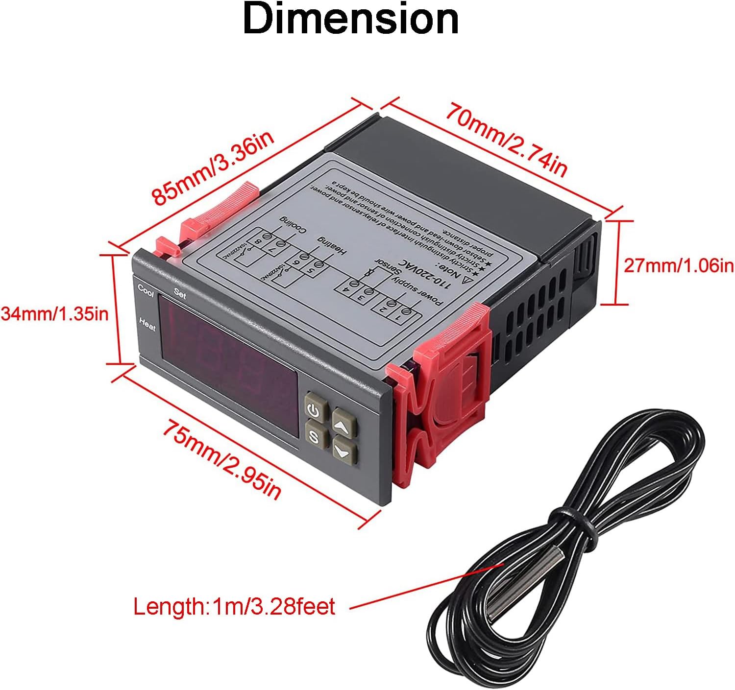
Figure 4.1: Product dimensions: 75mm (2.95in) width, 34mm (1.35in) height, 85mm (3.36in) depth, with a 1m (3.28ft) sensor cable.
| Parameter | Value |
|---|---|
| Temperature Measurement Range | -50 to 99 degrees Celsius |
| Controlled Temperature Range | -50 to 110 degrees Celsius |
| Measurement Accuracy | +/- 0.2 ℃ |
| Resolution | 0.1% |
| Control Accuracy | +/- 0.1 degrees Celsius |
| Sensor | NTC 10K L=1M waterproof probe |
| Power Consumption | <3W |
| Power Supply | AC/DC 110V-220V |
| Relay Contact Capacity (Cold) | 10A/220VAC |
| Relay Contact Capacity (Heat) | 10A/220VAC |
| Dimensions (L x W x H) | 75mm x 34.5mm x 85mm |
| Weight | 200g |
| Model Number | ZL499BLUM |
| Special Features | Illuminated, Calibration, Anti-delay protection |
5. Setup
Proper wiring is crucial for the safe and correct operation of the temperature controller. Refer to the diagram below for wiring methods.

Figure 5.1: Wiring diagrams for the temperature controller. Top diagram shows independent power supply for the load, bottom diagram shows same power supply for the load.
Wiring Instructions:
- Power Supply Connection: Connect the AC 110V-220V power supply to the designated terminals (L and N). Ensure correct polarity.
- Sensor Connection: Connect the NTC 10K waterproof probe to the sensor terminals. The sensor is replaceable via the 2P terminal.
- Heating Output: Connect your heating device (heater) to the 'Heating' relay output terminals.
- Cooling Output: Connect your cooling device (cooler) to the 'Cooling' relay output terminals.
- Load Power Supply: Depending on your setup, you can use an independent power supply for the load or the same power supply as the controller. Refer to Figure 5.1 for detailed connections.
Warning: Ensure all power is disconnected before performing any wiring. Incorrect wiring can lead to damage to the device or personal injury. If unsure, consult a qualified electrician.
6. Operating Instructions
The controller features a clear LED display and intuitive buttons for operation. Refer to Figure 3.2 for button identification.
Basic Operation:
- Power On/Off: Press the Power Switch button (⏻) to turn the device on or off.
- View Current Temperature: The large LED display shows the current temperature measured by the NTC sensor.
Setting Temperature and Modes:
- Enter Setting Mode: Press the 'S' (Setting) button. The display will flash, indicating you are in setting mode.
- Adjust Set Point: Use the UP (▲) and DOWN (▼) buttons to adjust the desired temperature set point.
- Set Difference Value (Hysteresis): After setting the main temperature, press 'S' again to cycle through other parameters, including the difference value (hysteresis). This value determines the temperature range around the set point before the relay switches. For example, if set to 2°C, and the set point is 25°C, heating will turn off at 25°C and turn on at 23°C (for heating mode).
- Select Mode (Heating/Cooling): The controller automatically switches between heating and cooling based on the relationship between the start and stop temperatures.
- Heating Mode: If the start temperature is set lower than the stop temperature.
- Cooling Mode: If the start temperature is set higher than the stop temperature.
- Temperature Calibration: The controller supports temperature calibration to fine-tune accuracy. Consult the full product manual (if available) for specific steps on accessing and adjusting calibration parameters.
- Exit Setting Mode: Press the 'S' button repeatedly until the display stops flashing, or wait for a few seconds for it to automatically exit.
Alarm Functions:
- The device will alarm if the measured temperature exceeds the set limit.
- An alarm will also activate if there is a sensor error, indicating a potential issue with the NTC probe connection or functionality.
7. Applications
The Greluma Digital Temperature Controller is versatile and suitable for a wide range of applications requiring precise temperature regulation.

Figure 7.1: Examples of common applications for the temperature controller.
Common Uses Include:
- Incubation: Maintaining stable temperatures for egg incubation in poultry farming.
- Wine Fermentation: Controlling the temperature during the wine fermentation process to ensure optimal conditions.
- Aquariums: Regulating water temperature in fish tanks to create a suitable environment for aquatic life.
- Refrigeration Systems: Managing cooling cycles in small refrigerators or chillers.
- Heating Systems: Controlling heating elements in various industrial or domestic setups.
- Greenhouses: Automating temperature control for plant growth.
8. Maintenance
To ensure the longevity and optimal performance of your Greluma Digital Temperature Controller, follow these maintenance guidelines:
- Cleaning: Regularly wipe the device with a soft, dry cloth. Do not use abrasive cleaners or solvents. Ensure the device is powered off before cleaning.
- Sensor Care: Keep the NTC sensor clean and free from debris. Avoid bending or damaging the sensor cable.
- Environmental Conditions: Operate the controller within its specified temperature and humidity ranges. Avoid exposure to excessive moisture, dust, or corrosive environments.
- Connection Checks: Periodically inspect all wiring connections to ensure they are secure and free from corrosion.
- Storage: If storing the device for an extended period, ensure it is kept in a dry, cool place away from direct sunlight.
9. Troubleshooting
This section addresses common issues you might encounter with the temperature controller.
| Problem | Possible Cause | Solution |
|---|---|---|
| Display is blank | No power supply; Incorrect wiring; Device malfunction. | Check power connections and voltage. Verify wiring according to Figure 5.1. If issues persist, contact support. |
| Temperature reading is inaccurate | Sensor not properly connected; Damaged sensor; Sensor calibration needed. | Ensure sensor is securely connected. Inspect sensor for physical damage. Perform temperature calibration if necessary. Replace sensor if damaged. |
| Controller not switching heating/cooling | Incorrect temperature set point or difference value; Wiring issue with load; Relay malfunction. | Verify set point and difference values are configured correctly. Check wiring to heating/cooling devices. Ensure load devices are functional. |
| Alarm sounds frequently | Temperature exceeding limits; Sensor error. | Check if the environment temperature is within the set limits. Verify sensor connection and integrity. Adjust alarm limits if applicable. |
| Buttons unresponsive | Temporary software glitch; Physical button damage. | Try power cycling the device. If buttons remain unresponsive, the device may require replacement. |
10. Warranty and Support
Information regarding product warranty and specific support contacts is not provided within this manual. For warranty claims, technical assistance, or spare parts availability, please refer to the product packaging, your purchase documentation, or contact the seller directly through the platform where the product was purchased.
Related Documents - ZL499BLUM (AC 220V Regulator Temperature 5-1)
 |
Small Frequency Converter Operation Manual: Installation, Operation, and Technical Specifications This operation manual provides detailed instructions for the installation, wiring, commissioning, and operation of small frequency converters. It includes technical specifications, safety precautions, and parameter tables for various models. |
 |
Harristian HRSTI 320 Серия: Руководство по эксплуатации преобразователя частоты Подробное руководство по эксплуатации для преобразователей частоты серии Harristian HRSTI 320. Ознакомьтесь с установкой, настройкой и безопасным использованием. |
 |
Harristian HRSTI 320 Series Operation Manual: Small Frequency Converters Explore the Harristian HRSTI 320 Series Operation Manual for detailed technical data, installation guides, operating procedures, and troubleshooting for their small frequency converters (VFDs), available in 220V and 400V models. |
 |
ATP1006-4 Time Switch: User Manual & Technical Specifications User manual for the Any Electronics ATP1006-4 Time Switch. Learn about its features, installation, wiring, programming, and specifications for controlling circuits with predetermined programs. |
 |
Instruction Manual for Small Universal Frequency Converter Detailed instruction manual for the Small Universal Frequency Converter, covering technical specifications, safety, installation, and operation for models like G1-220V and G3-380V. |
 |
Profi-Pumpe Inverter Pump Control: Parameters and Error Codes Comprehensive guide to parameter settings and error codes for Profi-Pumpe inverter pump control units (0.75kW - 7.5kW). Includes detailed tables for F0, F1, F2, FF, and d parameter groups, RS485 communication, and troubleshooting. |
Ask a question about this manual
Ask about setup, troubleshooting, compatibility, parts, safety, or missing instructions. Manuals+ will review the question and use this page’s manual context to help answer it.