1. Product Overview
The XYGStudy ST3215-HS is a high-performance bus servo motor designed for advanced robotic and automation projects. It features a large torque output of 20kg.cm at 12V, high speed of 106 RPM, and incorporates a 360-degree high-precision magnetic encoder for accurate position feedback. This servo motor supports two-way feedback and is switchable between servo mode and motor mode, offering versatility for various applications.
It is an ideal choice for building wheeled robots, 3D printers, quadruped robots, hexapod walkers, and robotic arms that require precise closed-loop speed control or stepping control.

Figure 1.1: The XYGStudy ST3215-HS Bus Servo Motor. This image displays the compact, black housing of the servo motor with its output shaft and mounting points visible.
2. Key Features
- High Torque & Speed: Delivers up to 20kg.cm torque at 12V and a no-load speed of 106 RPM (0.094 sec/60°).
- 360-Degree High Precision Magnetic Encoder: Provides accurate position sensing with 4096 resolution, enhancing control and extending motor lifetime.
- Two-Way Feedback: Offers real-time feedback on position, speed, torque lock, and working mode for advanced closed-loop control.
- Dual Operating Modes: Easily switchable between Servo Mode (precise rotation angle control) and Motor Mode (continuous rotation).
- UART Serial Bus Control: Capable of controlling up to 253 bus servo motors simultaneously, simplifying complex multi-servo systems.
- Acceleration Start-Stop Function: Allows setting speed and acceleration values for smoother motion transitions.
- Compact Structure Design: Features a dual shaft and low profile design, optimizing space and appearance.
- One-Button Calibration: Simplifies setting the middle position for the servo.
- Durable Construction: Utilizes nylon and fiberglass case, high-strength aluminum servo wheels, and high-precision copper and steel gears for reliability.
3. Specifications
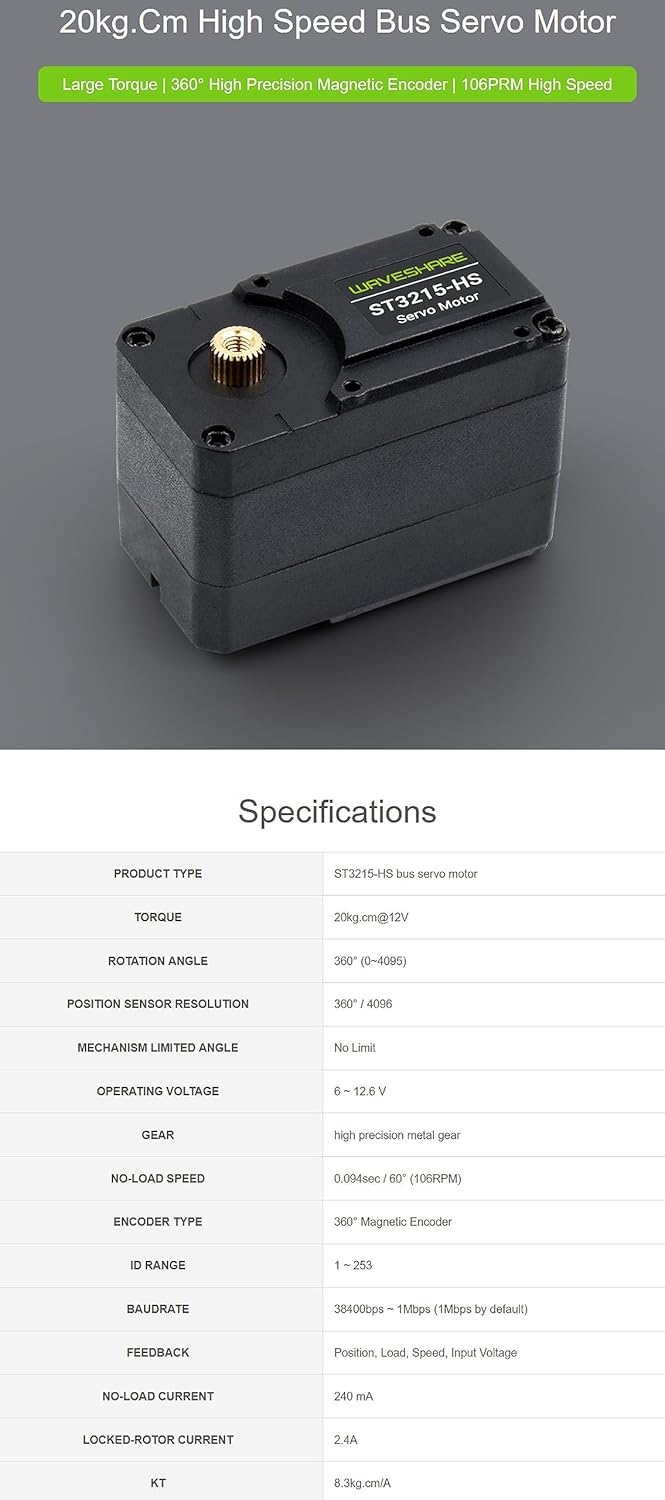
Figure 3.1: Detailed specifications of the ST3215-HS Bus Servo Motor.
| Parameter | Value |
|---|---|
| Product Type | ST3215-HS Bus Servo Motor |
| Torque | 20kg.cm @ 12V |
| Rotation Angle | 360° (0-4095) |
| Position Sensor Resolution | 360° / 4096 |
| Mechanism Limited Angle | No Limit |
| Operating Voltage | 6 - 12.6 V |
| Gear Type | High Precision Metal Gear |
| No-Load Speed | 0.094 sec/60° (106 RPM) |
| Encoder Type | 360° Magnetic Encoder |
| ID Range | 1 - 253 |
| Baud Rate | 38400 bps - 1 Mbps (1 Mbps by default) |
| Feedback | Position, Load, Speed, Input Voltage |
| No-Load Current | 240 mA |
| Locked-Rotor Current | 2.4 A |
| KT (Torque Constant) | 8.3 kg.cm/A |
| Material | Aluminum (Gear), Nylon & Fiberglass (Case) |
| UPC | 719704484404 |
4. Package Contents
The standard package for the ST3215-HS Bus Servo Motor includes the following items:
- ST3215-HS Servo Motor x1

Figure 4.1: Contents of the ST3215-HS Servo Motor package. This image shows the servo motor, mounting accessories (screws, servo wheels), and a connection cable.
5. Setup and Installation
5.1 UART Serial Bus Control
The ST3215-HS servo motor supports UART serial bus control, allowing multiple servos to be connected and controlled from a single communication bus. Up to 253 servo motors can be controlled simultaneously.

Figure 5.1: Diagram illustrating UART serial bus control for multiple servo motors. This image shows four servo motors connected in series to a control board, demonstrating the bus communication setup.
Note: While one channel UART can control up to 253 bus servo motors, ensure the power supply is sufficient when using many servo motors due to high power demands. The servo driver board is not included.
5.2 Installing Flat Key Shaft Flange
The servo is designed to support the installation of flat key shaft flanges, which allows for easy attachment of various transmission parts like wheels or robotic linkages.

Figure 5.2: Illustration of the flat key shaft flange and compatible parts. This image shows the servo motor with an attached flat key shaft flange, alongside examples of wheels and other components that can be mounted.
Note: The flat key shaft flange and wheels are not included with the servo motor.
6. Operating Instructions
6.1 Dual Modes: Servo or Motor
The ST3215-HS servo motor can operate in two distinct modes:
- Servo Mode: Provides precise control over the rotation angle, typically within a defined range.
- Motor Mode: Enables continuous rotation, suitable for applications requiring constant movement.

Figure 6.1: Visual representation of the servo operating in precise rotation angle control (Servo Mode) and continuous rotation (Motor Mode). This image shows a mobile phone interface controlling the servo in both modes.
6.2 One-Button Middle Position Calibration
To calibrate the middle position of the servo motor, follow these steps:
- In the default program, a hotspot will be created automatically after the servo driver board is turned on. Use your mobile phone to connect to this hotspot, open the browser, and enter the IP address to access the control interface.
- Click 'Release' to unlock the servo, then turn the servo motor to the desired middle position.
- Click 'Set Middle Position' and confirm.
- To verify, turn the servo motor to any angle, then click 'Middle'. The servo motor should automatically return to the initially set middle position.

Figure 6.2: Step-by-step guide for calibrating the servo's middle position using a mobile interface. This image illustrates the process from connecting to the hotspot to setting and verifying the middle position.
6.3 Two-Way Feedback
The ST3215-HS servo motor provides real-time two-way feedback, allowing users to monitor critical parameters such as position, load, speed, and input voltage. This feature is essential for advanced closed-loop control systems.
6.4 Open Source Control Program
An open-source web control demo of the servo driver board and a secondary development tutorial are available. These resources can be used for remote setting and control of the servo motor, and to quickly build custom projects. A 3D model is also provided.
7. Application Examples
The ST3215-HS servo motor is suitable for a wide range of applications requiring accurate closed-loop speed control or stepping control. Examples include:
- Wheeled Robots: For precise steering and movement.
- 3D Printers: For accurate axis control.
- Quadruped and Hexapod Robots: For complex leg movements and balance.
- Robotic Arms: For multi-joint articulation and precise manipulation.

Figure 7.1: Examples of robotic applications utilizing the ST3215-HS servo motor. This image displays an open-source quadruped robot model and robotic arm configurations, demonstrating the servo's versatility.
8. Maintenance
To ensure the longevity and optimal performance of your ST3215-HS Bus Servo Motor, consider the following general maintenance guidelines:
- Keep Clean: Regularly clean the exterior of the servo to prevent dust and debris accumulation, especially around moving parts and ventilation openings.
- Avoid Overload: Do not exceed the specified torque and voltage limits to prevent damage to the motor and gears.
- Proper Storage: Store the servo in a dry, cool environment away from direct sunlight and extreme temperatures.
- Inspect Connections: Periodically check all electrical connections for secure fit and signs of wear or corrosion.
- Lubrication: The internal gears are pre-lubricated. Avoid disassembling the servo unless necessary, as this may void any warranty and affect performance.
9. Troubleshooting
If you encounter issues with your ST3215-HS Bus Servo Motor, consider the following troubleshooting steps:
- No Movement:
- Check power supply voltage and current. Ensure it meets the 6-12.6V requirement and can provide sufficient current (e.g., 2.4A locked-rotor current).
- Verify all wiring connections are correct and secure.
- Confirm the servo ID is correctly set and matches the control command.
- Ensure the control signal (UART) is being sent correctly and at the appropriate baud rate.
- Erratic Movement or Incorrect Position:
- Recalibrate the middle position as described in Section 6.2.
- Check for mechanical obstructions or excessive load on the servo shaft.
- Inspect the magnetic encoder for any physical damage or interference.
- Ensure the control commands are within the servo's operational range.
- Overheating:
- Reduce the load on the servo.
- Ensure adequate ventilation around the servo.
- Check for continuous stalled conditions or rapid, high-frequency movements that can generate excessive heat.
For persistent issues, refer to the open-source development tutorial or contact XYGStudy customer support.
10. Dimensions
The physical dimensions of the ST3215-HS Bus Servo Motor are provided below for integration into your projects.
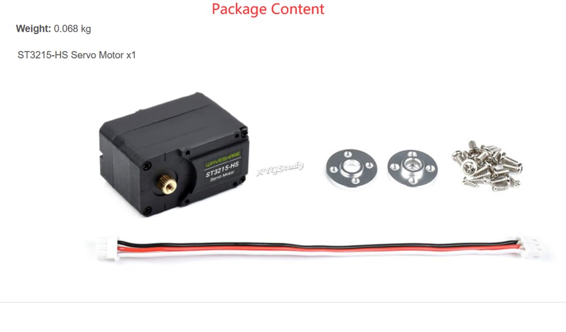
Figure 10.1: Outline dimensions of the ST3215-HS Bus Servo Motor in millimeters. This image provides detailed measurements for the servo's length, width, height, and mounting hole positions.
11. Warranty and Support
For warranty information, technical support, or additional resources (such as detailed datasheets or programming guides), please contact XYGStudy directly through your purchase platform or their official website. Please have your product model (ST3215-HS) and purchase details ready when contacting support.