Dpofirs Dpofirstik8g2vqym
Dpofirs Desktop Motherboard User Manual
Model: Dpofirstik8g2vqym
1. Introduction
This manual provides comprehensive instructions for the installation, operation, and maintenance of the Dpofirs Desktop Motherboard. This Micro ATX motherboard is designed for gaming and general computing, featuring an LGA 1155 CPU slot, dual-channel DDR3 memory support, and an M.2 NVMe NGFF interface. Please read this manual thoroughly before use to ensure proper functionality and longevity of your product.

Figure 1: Overview of the Dpofirs Desktop Motherboard. This image displays the full motherboard from an angled perspective, highlighting its various components and compact Micro ATX form factor.
2. Setup and Installation
Follow these steps carefully to install your Dpofirs Desktop Motherboard and its components.
2.1. Component Identification
Familiarize yourself with the layout of the motherboard before beginning installation.
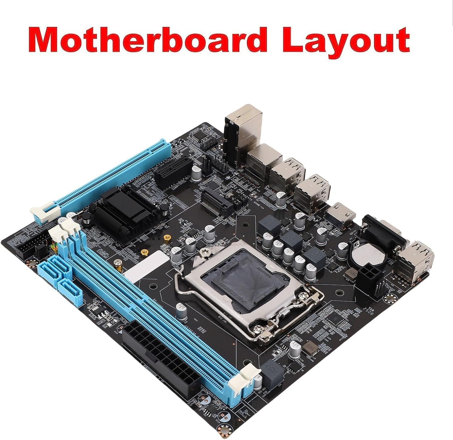
Figure 2: Motherboard Layout. This diagram illustrates the key areas and connectors on the motherboard, including the CPU socket, RAM slots, PCIe slots, and I/O ports.
2.2. CPU Installation (LGA 1155)
- Prepare the Socket: Gently lift the load lever on the LGA 1155 CPU socket. Open the metal load plate.
- Align the CPU: Carefully align the CPU with the socket, ensuring the golden triangle on the CPU matches the triangle mark on the socket. Do not force the CPU into place.
- Secure the CPU: Lower the load plate and press down the load lever until it clicks into place.
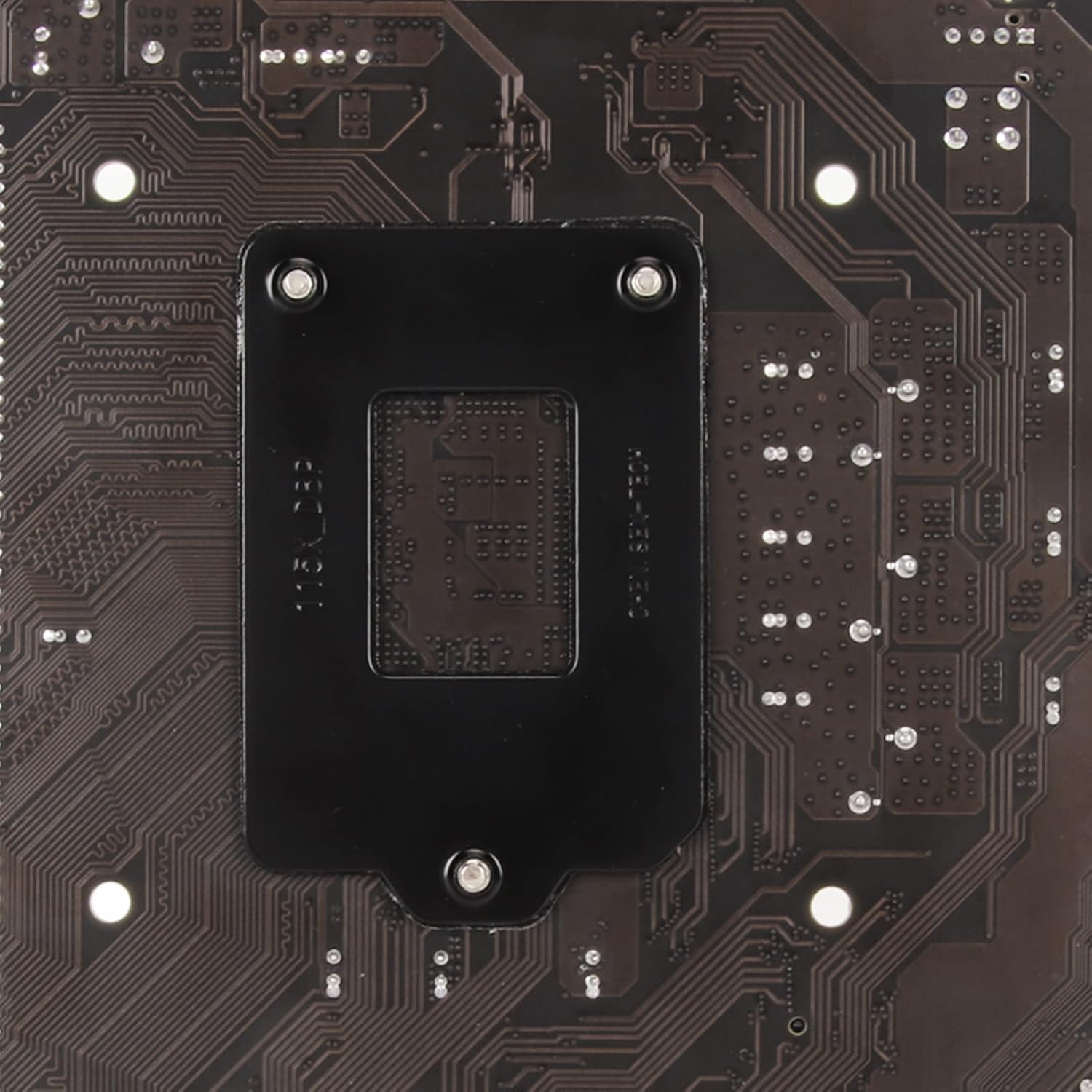
Figure 3: LGA 1155 CPU Socket. A detailed view of the CPU socket, showing the mechanism for securing the processor.
2.3. RAM Installation (DDR3)
This motherboard supports Dual Channel DDR3 memory. Install memory modules into the designated DDR3 slots.
- Open Latches: Open the white latches at both ends of the DDR3 memory slot.
- Align Module: Align the notch on the DDR3 memory module with the key in the memory slot.
- Insert Module: Press down firmly on both ends of the memory module until the latches click into place.
2.4. M.2 NVMe/NGFF SSD Installation
The motherboard features an M.2 slot supporting both NVMe and NGFF SSDs. Use the provided jumper wire to select the desired mode (PCIe or SATA2.0 channel).
- Locate M.2 Slot: Identify the M.2 slot on the motherboard.
- Insert SSD: Insert the M.2 SSD into the slot at a slight angle.
- Secure SSD: Gently push down the SSD and secure it with the provided screw.
- Configure Jumper: Refer to the motherboard diagram for the M.2 jumper settings to select between NVMe (PCIe) or NGFF (SATA2.0) mode.
2.5. Power Connections
Connect the power supply unit (PSU) to the motherboard.
- 24-Pin ATX Power: Connect the main 24-pin ATX power connector from the PSU to the corresponding socket on the motherboard.
- 4-Pin ATX 12V Power: Connect the 4-pin ATX 12V power connector (CPU power) from the PSU to the socket near the CPU.
2.6. Peripheral Connections
Connect other essential components and peripherals.
- SATA Devices: Connect SATA data cables from your storage drives (HDDs/SSDs) to the 4 SATA 2.0 ports on the motherboard.
- Front Panel Connectors: Connect the power switch, reset switch, HDD LED, power LED, and front USB/audio headers from your PC case to the corresponding pins on the motherboard. Refer to the motherboard manual for pinout details.
- Expansion Cards: Install graphics cards into the PCIe X16 slot and other expansion cards into the PCIe X1 slot as needed.
- I/O Shield: Install the I/O shield into your PC case before mounting the motherboard.

Figure 4: Included Accessories. This image shows the motherboard alongside its I/O shield and a SATA data cable, which are typically included for installation.
3. Operating Instructions
3.1. Initial Boot-up
- Connect Peripherals: Ensure all necessary peripherals (monitor, keyboard, mouse) are connected to the motherboard's I/O ports.
- Power On: Turn on the power supply and press the power button on your PC case.
- BIOS/UEFI Access: During boot-up, repeatedly press the DEL or F2 key (common keys, may vary) to enter the BIOS/UEFI setup utility.
3.2. BIOS/UEFI Configuration
The BIOS/UEFI allows you to configure system settings, boot order, and hardware parameters.
- Boot Order: Set the boot priority to your desired operating system installation media (USB drive, DVD drive) or existing storage drive.
- Date and Time: Adjust the system date and time.
- SATA Mode: Ensure SATA mode is set correctly (e.g., AHCI for modern SSDs).
- Save and Exit: After making changes, save the configuration and exit the BIOS/UEFI. The system will restart.
3.3. Operating System Installation
Install your preferred operating system (e.g., Windows, Linux) by following its specific installation prompts.
4. Maintenance
Regular maintenance helps ensure the longevity and stable performance of your motherboard.
- Dust Removal: Periodically clean dust from the motherboard and other internal components using compressed air. Ensure the system is powered off and unplugged before cleaning.
- BIOS/UEFI Updates: Check the manufacturer's website for BIOS/UEFI updates. Updates can improve compatibility, stability, and performance. Follow the update instructions carefully to avoid damaging the motherboard.
- Driver Updates: Keep your device drivers (chipset, audio, LAN, graphics) updated to the latest versions for optimal performance and stability.
- Environmental Control: Operate the computer in a well-ventilated area, away from direct sunlight, excessive heat, and humidity.
5. Troubleshooting
This section provides solutions to common issues you might encounter.
| Problem | Possible Cause | Solution |
|---|---|---|
| System does not power on. | Loose power connections, faulty PSU, incorrect front panel wiring. |
|
| No display on monitor. | Loose display cable, faulty GPU/integrated graphics, RAM issues. |
|
| System reboots unexpectedly or crashes. | Overheating, unstable power, faulty components (RAM, CPU). |
|
| M.2 SSD not detected. | Incorrect M.2 jumper setting, incompatible SSD, loose connection. |
|
6. Technical Specifications
Detailed specifications for the Dpofirs Desktop Motherboard.
| Feature | Description |
|---|---|
| Model | Dpofirstik8g2vqym |
| CPU Socket | LGA 1155 (Supports Intel i3/i5/i7 2nd Gen, Pentium, Celeron Series) |
| Chipset | Intel H610 |
| RAM Technology | DDR3 Non ECC |
| Memory Slots | 2 |
| Max RAM Capacity | 16GB |
| Memory Frequency | 1066/1333/1600MHz |
| Storage Ports | 4 x SATA 2.0 (3GB/s), 1 x M.2 NVMe/NGFF Slot (dual mode support) |
| Expansion Slots | 1 x PCIe X16, 1 x PCIe X1 |
| Video Output | 1 x VGA Port, 1 x HD Multimedia Interface Port |
| USB Ports | 6 x USB 2.0 (Rear I/O), 2 x USB 2.0 Headers (supports 4 additional USB 2.0 ports) |
| LAN | 10/100Mbps RJ45 Port |
| Audio | Onboard ALC 6 Channel HD Audio Codec, 3-in-1 Audio Port (Line In/Out/Mic In) |
| Power Connectors | 1 x 24-Pin ATX, 1 x 4-Pin ATX 12V |
| Form Factor | Micro ATX (17 x 19cm / 6.7 x 7.5in) |
| Battery | 240mAh CR2032 Battery (Inbuilt) |
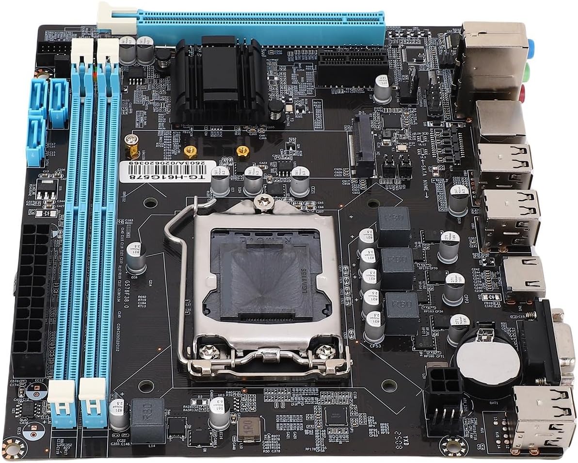
Figure 5: Motherboard Top View. This image provides a clear top-down view of the motherboard, detailing the arrangement of its various ports, slots, and integrated circuits.
7. Warranty and Support
For warranty information and technical support, please refer to the following:
- Warranty: Specific warranty terms and conditions are typically provided with your purchase documentation. Please retain your proof of purchase for warranty claims.
- Technical Support: For technical assistance, troubleshooting beyond this manual, or service requests, please contact Dpofirs customer support through their official website or the retailer where the product was purchased.
- Online Resources: Visit the Dpofirs Store on Amazon for additional product information and updates.
Ask a question about this manual
Ask about setup, troubleshooting, compatibility, parts, safety, or missing instructions. Manuals+ will review the question and use this page’s manual context to help answer it.