1. Introduction
This manual provides essential information for the installation, operation, and maintenance of the BAYDE 2085-OF4 Micro800 Analog Output Module. This module is designed to expand the capabilities of Allen-Bradley Micro800 controllers by providing analog output signals for various industrial applications. Please read this manual thoroughly before attempting to install or operate the module.
2. Safety Information
Always observe the following safety precautions to prevent personal injury and damage to the equipment:
- Ensure all power is disconnected before installing, wiring, or servicing the module.
- Only qualified personnel should perform installation and maintenance procedures.
- Follow all local and national electrical codes.
- Protect the module from moisture, dust, and extreme temperatures.
- Verify correct wiring before applying power to prevent damage to the module or connected devices.
3. Product Overview
The BAYDE 2085-OF4 is an analog output module specifically designed for the Micro800 series of programmable logic controllers. It provides four analog output channels, allowing the controller to send variable voltage or current signals to external devices such as actuators, variable frequency drives, or indicators. This module enhances control precision in industrial automation systems.

Image 3.1: Rear view of the 2085-OF4 module, showing the product label with specifications and certifications.
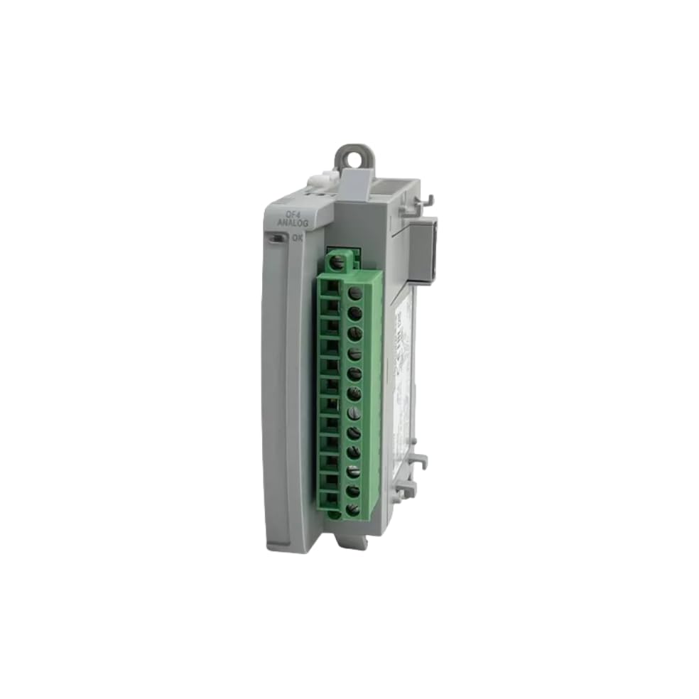
Image 3.2: Side view of the 2085-OF4 module, illustrating its compact design and terminal block.
4. Setup and Installation
Proper installation is crucial for the reliable operation of the 2085-OF4 module.
4.1 Unpacking
Carefully remove the module from its packaging. Inspect for any signs of damage during transit. If damage is found, contact your supplier immediately.

Image 4.1: The 2085-OF4 module as received in its factory-sealed packaging.

Image 4.2: Close-up of the factory seal and product label on the module's box.
4.2 Mounting
The 2085-OF4 module is designed to be mounted alongside a Micro800 controller or other Micro800 expansion modules on a DIN rail. Ensure sufficient clearance for ventilation and wiring.
- Align the module with the DIN rail.
- Press firmly to snap the module onto the DIN rail.
- Slide the module into position next to the controller or adjacent module, ensuring the inter-module connectors engage properly.
4.3 Wiring
Connect the analog output signals to the appropriate terminals on the module. Refer to the wiring diagram provided with your Micro800 controller documentation for specific terminal assignments. The module supports various output types, including -10-10VDC, 0-10VDC, 0-20mA, and 4-20mA. Ensure proper shielding for analog signal cables to minimize noise interference.
4.4 Power Connection
The module draws power from the Micro800 controller's backplane. Ensure the controller's power supply is adequate for the total current draw of all connected modules.
5. Operating Instructions
Once installed and wired, the 2085-OF4 module operates under the control of the Micro800 PLC program. The module converts digital values from the PLC into corresponding analog voltage or current signals.
5.1 Configuration
The module's output ranges and scaling are configured within the Micro800 programming software (e.g., Connected Components Workbench). This involves:
- Selecting the desired output type (voltage or current).
- Defining the output range (e.g., 0-10V, 4-20mA).
- Setting up scaling parameters to convert PLC integer values to the physical analog output.
5.2 Analog Output Control
In the PLC program, write values to the module's output registers. These values are then converted by the 2085-OF4 into the specified analog signal. For example, a PLC value of 0 might correspond to 0V or 4mA, and a maximum PLC value might correspond to 10V or 20mA, depending on the configured scaling.
6. Maintenance
The 2085-OF4 module is designed for robust industrial use and requires minimal maintenance.
- Periodic Inspection: Regularly inspect the module and its wiring for any signs of damage, loose connections, or corrosion.
- Cleaning: Keep the module free from dust and debris. Use a soft, dry cloth for cleaning. Do not use solvents or abrasive cleaners.
- Environmental Control: Ensure the operating environment remains within the specified temperature and humidity ranges to prolong the module's lifespan.
7. Troubleshooting
If you encounter issues with your 2085-OF4 module, consider the following troubleshooting steps:
- No Analog Output:
- Verify power to the Micro800 controller.
- Check module status indicators (if present) for error codes.
- Confirm correct wiring to the output device.
- Review PLC program logic and module configuration in the programming software.
- Incorrect Analog Output:
- Check scaling parameters in the PLC program.
- Verify the output range setting in the module configuration matches the connected device's requirements.
- Inspect for electrical noise or interference on analog signal lines.
- Test the output with a multimeter to confirm the module's signal.
- Module Not Detected by PLC:
- Ensure the module is properly seated on the DIN rail and connected to the backplane.
- Check for physical damage to the module or backplane connector.
- Verify the module is correctly added to the PLC project in the programming software.
8. Specifications
Key technical specifications for the BAYDE 2085-OF4 Micro800 Analog Output Module:
| Feature | Description |
|---|---|
| Model Number | 2085-OF4 |
| Product Type | Micro800 Analog Output Module |
| Output Channels | 4 |
| Output Types | -10-10VDC, 0-10VDC, 0-20mA, 4-20mA |
| Backplane Voltage | 5VDC |
| Backplane Current (5VDC) | 160mA |
| Backplane Voltage | 24VDC |
| Backplane Current (24VDC) | 120mA |
| Operating Temperature | -20°C to +65°C |
| Manufacturer | BAYDE |
| UPC | 614160207065 |
9. Warranty and Support
BAYDE ensures the quality of its products. All 2085-OF4 modules are original new and produced by the brand's original factory. For any technical assistance, inquiries, or specific model requirements, please consult your supplier or the manufacturer directly.