1. Introduction
This manual provides essential information for the safe and effective installation, operation, and maintenance of the SPRECHER Schuh CA-3-9-10 Contactor. This device is a 3-pole, 25 Amp contactor designed for controlling electrical loads, featuring a 120V coil and an integrated normally open (N.O.) auxiliary contact. Please read this manual thoroughly before proceeding with any procedures.
2. Safety Information
WARNING: Electrical shock hazard. Only qualified and authorized personnel should install, operate, or service this equipment. Failure to observe these precautions could result in severe injury or death.
- Always disconnect and lock out all power sources before working on the contactor or connected equipment.
- Ensure proper grounding of all electrical components.
- Use appropriate personal protective equipment (PPE) such as insulated gloves and safety glasses.
- Verify all wiring connections are secure and conform to local and national electrical codes.
- Do not exceed the specified voltage and current ratings of the contactor.
3. Product Overview
The SPRECHER Schuh CA-3-9-10 Contactor is a robust industrial component designed for reliable switching of electrical circuits. It features three main power poles, a 120V AC coil for control, and one built-in normally open (N.O.) auxiliary contact for signaling or interlocking purposes.
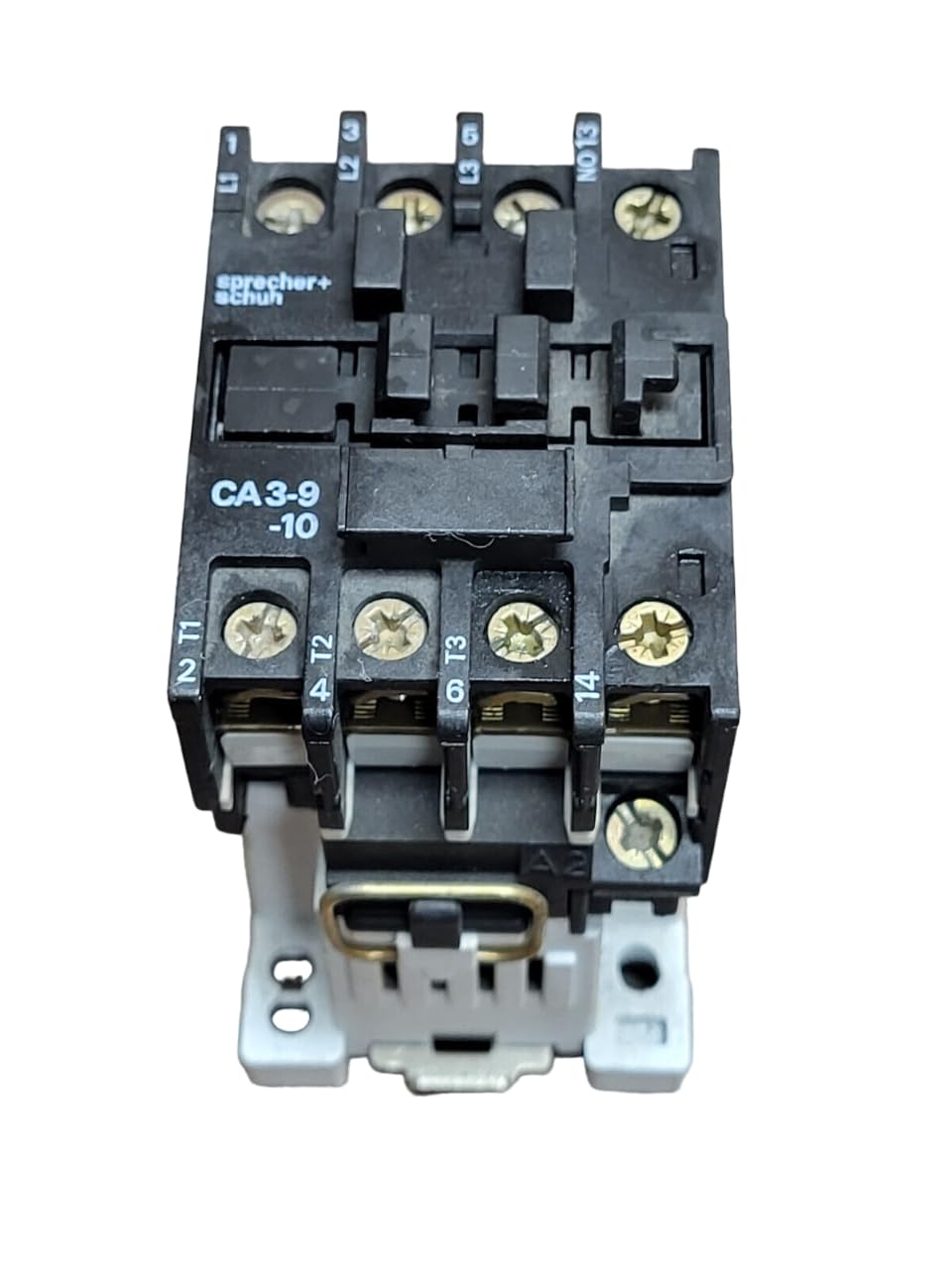
Figure 3.1: Front View of Contactor. This image displays the front of the SPRECHER Schuh CA-3-9-10 contactor, showing the main power terminals labeled L1, L2, L3 at the top for incoming power, and T1, T2, T3 at the bottom for outgoing load connections. The auxiliary contact is visible with terminals NO13 and 14. The model number 'CA3-9-10' is clearly marked on the front casing.

Figure 3.2: Side View with Specifications. This image shows a side view of the contactor, highlighting the product label with detailed electrical specifications. Information such as voltage ratings (e.g., 110V, 120V, 230V, 400V), horsepower (HP) ratings for various voltages, and current ratings (e.g., 25 Amps) are visible. The coil voltage selection for 110V 50Hz and 120V 60Hz is also indicated.
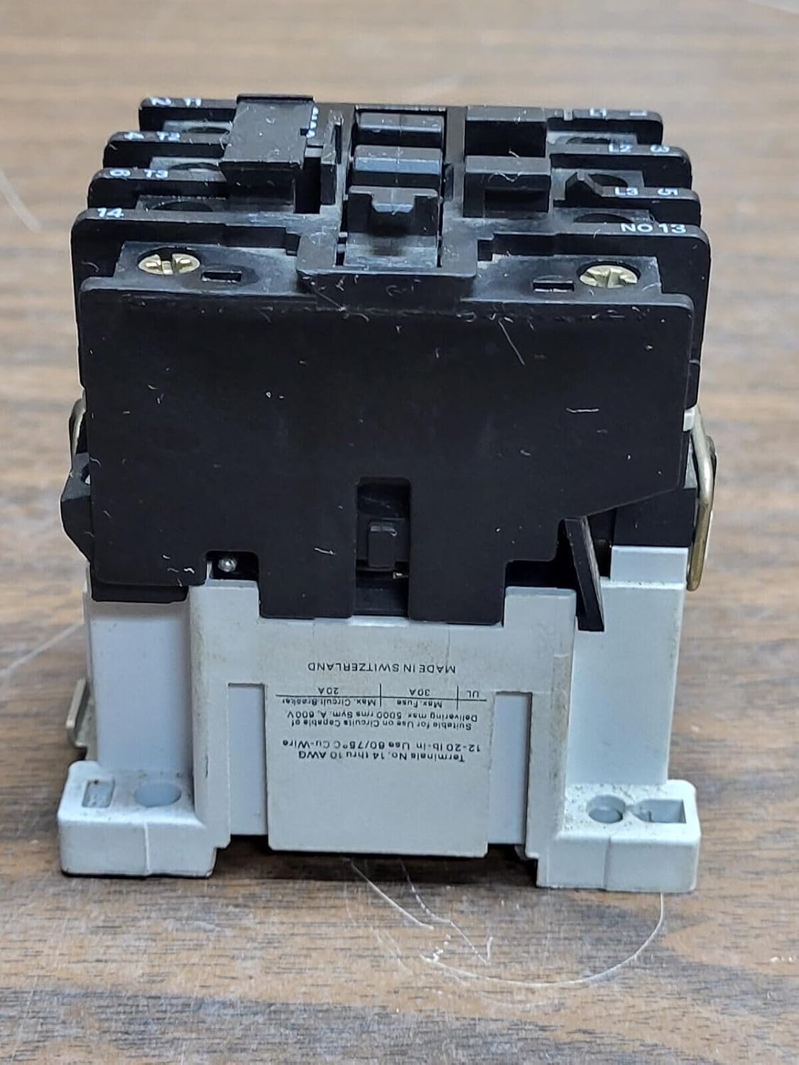
Figure 3.3: Bottom View of Contactor. This image provides a view of the bottom of the contactor, revealing the mounting mechanism and additional manufacturing details. Text indicating "MADE IN SWITZERLAND" is visible, along with specifications for terminal wire sizes (e.g., 14-10 AWG) and temperature ratings.

Figure 3.4: Side View with Coil Voltage Details. This image presents another side angle of the contactor, emphasizing the coil voltage markings. The labels clearly show options for 110V 50Hz and 120V 60Hz, which are critical for proper control circuit design. Terminal A1 for the coil connection is also visible.
4. Installation and Setup
The CA-3-9-10 contactor is designed for plug-in mounting, facilitating straightforward installation in compatible enclosures or panels.
4.1 Mounting
- Ensure the mounting surface is clean, dry, and free from vibrations.
- Secure the contactor using its integrated plug-in mechanism into a suitable base or DIN rail adapter (if applicable and purchased separately).
- Allow adequate clearance around the contactor for ventilation and wiring access.
4.2 Wiring
Refer to the wiring diagram provided with your system or equipment. The following are general guidelines:
- Main Power Circuit: Connect the incoming power lines to terminals L1, L2, L3. Connect the load lines to terminals T1, T2, T3. Ensure wire gauges are appropriate for the 25 Amp rating and local electrical codes.
- Control Circuit: Connect the 120V AC control voltage to the coil terminals (typically A1 and A2). Ensure the control voltage matches the coil rating to prevent damage.
- Auxiliary Contact: The N.O. auxiliary contact (terminals NO13 and 14) can be used for feedback, interlocking, or other control functions. Connect these terminals as required by your control scheme.
- Tighten all terminal screws to the manufacturer's specified torque settings to ensure secure electrical connections and prevent overheating.
5. Operation
The SPRECHER Schuh CA-3-9-10 Contactor operates by energizing its electromagnetic coil, which in turn closes the main power contacts and the auxiliary contact.
- When the 120V AC control voltage is applied to the coil terminals (A1-A2), the coil generates a magnetic field.
- This magnetic field pulls the armature, causing the main power contacts (L1-T1, L2-T2, L3-T3) to close, thereby connecting the power source to the load.
- Simultaneously, the normally open (N.O.) auxiliary contact (NO13-14) also closes, providing a signal or completing an auxiliary circuit.
- When the control voltage is removed from the coil, the magnetic field collapses, and springs return the contacts to their original open position, disconnecting power from the load and opening the auxiliary contact.
6. Maintenance
Regular maintenance helps ensure the longevity and reliable operation of the contactor.
6.1 Inspection Schedule
- Perform visual inspections quarterly or more frequently in harsh environments.
- Conduct functional tests annually to verify proper operation.
6.2 Inspection Procedures
- WARNING: Disconnect all power before inspection.
- Check for signs of overheating, such as discoloration or melted insulation on wires and terminals.
- Inspect contacts for excessive wear, pitting, or carbon buildup. Minor pitting is normal; severe damage may require replacement.
- Verify all terminal connections are tight. Loose connections can cause resistance and heat buildup.
- Ensure the contactor mechanism moves freely without obstruction.
- Clean any dust or debris from the contactor using a dry, non-conductive brush or compressed air.
7. Troubleshooting
If the contactor is not functioning as expected, perform the following checks:
| Problem | Possible Cause | Solution |
|---|---|---|
| Contactor does not pull in (contacts do not close) |
|
|
| Contactor hums loudly or chatters |
|
|
| Contactor contacts overheat or weld |
|
|
8. Specifications
| Parameter | Value |
|---|---|
| Model | CA-3-9-10 |
| Manufacturer | SPRECHER SCHUH |
| Current Rating | 25 Amps |
| Number of Poles | 3 (Main Power) |
| Auxiliary Contacts | 1 N.O. (Normally Open) |
| Coil Voltage | 120V AC (50/60 Hz) |
| Mounting Type | Plug-In Mount |
| Circuit Breaker Type | Standard |
9. Warranty and Support
This SPRECHER Schuh contactor is typically covered by a manufacturer's warranty against defects in materials and workmanship. For specific warranty terms, duration, and claim procedures, please refer to the documentation provided at the time of purchase or contact the original seller or SPRECHER SCHUH directly.
For technical support, troubleshooting assistance beyond this manual, or spare parts inquiries, please contact your authorized SPRECHER SCHUH distributor or the seller from whom the product was purchased. When contacting support, please have the model number (CA-3-9-10) and any relevant purchase information readily available.