1. Introduction and Overview
The UNI-T UT273+ is a professional clamp ground resistance tester designed for accurate measurement of earth resistance and current. It features a large black screen for clear readings, a robust jaw size, and strong anti-interference capabilities, making it suitable for various industrial and scientific applications. This manual provides detailed instructions for the safe and effective use of your UT273+ device.

Figure 1.1: Overview of the UNI-T UT273+ with its key features highlighted, including resistance and current measurement ranges, high-definition display, and data storage capabilities.
2. Key Features
- Earth Resistance Test: Measures resistance from 0 to 600Ω.
- Current Test: Measures current from 0 to 20A.
- Large Black Screen: Features a 32mm display for enhanced readability.
- Large Jaw Size: Accommodates various grounding and busbar sizes (55mm*32mm).
- Strong Anti-Interference: Ensures stable and accurate measurements in challenging environments.
- Alarm Function: Settable alarm for out-of-range measurements.
- Data Storage: Stores up to 500 sets of measurement data.
- USB Data Transfer: Allows for easy transfer of stored data to a computer for analysis.
- Quick Self-Check Function: Provides immediate operational status.
3. Package Contents
Upon opening the package, please verify that all items listed below are present and in good condition:
- UNI-T UT273+ Clamp Ground Resistance Tester
- Hard Carrying Case
- USB Data Cable
- User Manual
- Calibration Loop (Inspection Ring)
- Batteries (4x 1.5V AA, included)

Figure 3.1: The complete package contents of the UNI-T UT273+ Clamp Ground Resistance Tester.
4. Setup
4.1 Battery Installation
The UT273+ requires four 1.5V AA batteries for operation. To install or replace batteries:
- Locate the battery compartment on the back of the device.
- Use a screwdriver to open the battery cover.
- Insert four 1.5V AA batteries, ensuring correct polarity (+/-).
- Securely close the battery cover.

Figure 4.1: Rear view of the UT273+ indicating the battery compartment. Always ensure batteries are installed with correct polarity.
4.2 Device Components
Familiarize yourself with the main components of the UT273+:

Figure 4.2: Labeled diagram of the UT273+ highlighting its key components such as the clamp head, LCD display, control buttons (MODE, SET, AL, MEM), data lock/storage button, and data transmission interface.
5. Operating Instructions
5.1 Basic Operation
- Power On/Off: Press the Power button to turn the device on or off.
- Mode Selection: Use the MODE key to switch between different measurement modes (e.g., Earth Resistance, Current).
- Data Lock/Storage: Press the HOLD button to freeze the current reading. Press the MEM button to store the current reading.
- Alarm Setting: Use the AL button to set or clear alarm thresholds.
5.2 Earth Resistance Measurement Principle
The basic principle of the clamp ground resistance meter is to measure the loop resistance. The jaw part of the clamp meter is composed of a voltage coil and a current coil. The voltage coil provides the excitation signal, and a potential V is induced in the circuit under test. Under the action of the potential V, a current I will be generated in the circuit under test. The clamp meter measures V and I, and through the formula R=V/I, the measured resistance R can be obtained.

Figure 5.1: Illustration of the measuring principle, showing the relationship between potential (V), current (I), and resistance (R).
5.3 Measurement Methods
5.3.1 Single-Point Grounding System (Two-Point Method)
Find an independent grounding body RB with good grounding near the tested grounding body RA (such as a nearby metal water pipe, fire hydrant, or roof lightning protection belt). Connect RA and RB with a test wire. Generally, the grounding resistance of water pipes and fire hydrants is very small and can be overlooked. If the meter reading during the 2-point test is less than the required value of the tested grounding system, both RA and RB are qualified.
5.3.2 Single-Point Grounding System (Three-Point Method)
Find 2 other existing grounding points near the grounding point to be tested or hit 2 auxiliary grounding pins to match the grounding. Into 3 grounding points. The deeper the auxiliary grounding needle, the better, generally 0.7 meters deep. The 3-point method requires a test line (Generally, a wire of 1.5-2.5 square meters is sufficient, and the insulation at both ends should be removed) and 2 auxiliary grounding pins.

Figure 5.2: Visual representation of the two-point and three-point grounding measurement methods.
5.4 Data Transfer
After the measurement is completed, plug in the standard data cable and turn on the installed host computer software. The instrument will automatically connect and communicate with the computer. Click to get the data. Data can be exported from the data stored in the meter, saving time for comparative analysis.
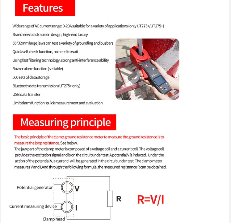
Figure 5.3: The UT273+ connected via USB for data transfer to a computer, illustrating the software interface for data output and saving.
6. Maintenance
To ensure the longevity and accuracy of your UNI-T UT273+:
- Cleaning: Wipe the device with a soft, dry cloth. Do not use abrasive cleaners or solvents.
- Storage: Store the meter in its carrying case in a cool, dry place when not in use. Avoid extreme temperatures and humidity.
- Battery Replacement: Replace batteries promptly when the low battery indicator appears to prevent inaccurate readings or device malfunction. Remove batteries if the device will not be used for an extended period.
- Calibration: Regular calibration by qualified personnel is recommended to maintain measurement accuracy, especially for professional applications.
7. Troubleshooting
This section addresses common issues you might encounter with your UT273+.
| Problem | Possible Cause | Solution |
|---|---|---|
| Device does not power on. | Dead or incorrectly installed batteries. | Check battery polarity or replace with new batteries. |
| Inaccurate readings. | Low battery, environmental interference, or improper measurement technique. | Replace batteries. Ensure proper grounding and minimize external interference. Refer to measurement method section. Consider professional calibration. |
| Data transfer failure. | Loose USB connection, software not running, or driver issues. | Ensure USB cable is securely connected. Verify host computer software is open and running. Install necessary drivers if prompted. |
| Display shows "OL" (Overload). | Measurement exceeds the device's range. | Ensure the measurement is within the specified range of the UT273+. |
8. Specifications
The following table outlines the technical specifications for the UNI-T UT273+ Clamp Ground Resistance Tester:

Figure 8.1: Detailed specifications for the UT273+ and other related models, including measurement ranges, accuracy, and general features.
- Product Dimensions: 6.5 x 4.33 x 4.72 inches (16.5 x 11 x 12 cm)
- Item Weight: 1.32 Pounds (0.6 Kilograms)
- Power Source: Battery Powered (4x 1.5V AA batteries)
- Color: Multicolored
- Manufacturer: UNI-Trend
- First Available Date: August 6, 2023
9. Warranty and Support
UNI-T (Uni-Trend Technology) has been a developer, manufacturer, and marketer of reliable testing, measuring, and inspecting products since 1988. For specific warranty information, technical support, or service inquiries, please contact UNI-T directly through their official channels.
Official Website: http://www.uni-trend.com.cn
Please refer to the product packaging or the official UNI-T website for the most up-to-date contact information and warranty terms applicable to your region.