1. Introduction
The UNI-T UT3513 Micro Ohm Meter is a precision instrument designed for accurate DC resistance measurements. Part of the UT3510 series, this device offers a professional sorting function, allowing for HI/IN/LO resistance judgments. Measurement results are displayed on a clear screen, indicated by a buzzer, and can be output via external I/O. It features a 4.3-inch LCD, 0.05% accuracy, and a resistance test range of 1µΩ to 20kΩ.
This manual provides essential information for the safe and effective operation, setup, and maintenance of your UT3513 Micro Ohm Meter.

Figure 1: Front view of the UT3510 Series Micro Ohm Meter (UT3516 shown, UT3513 is similar).
2. Setup
2.1 Unpacking and Inspection
Carefully unpack the instrument and inspect it for any signs of damage. Ensure all accessories listed in the packing list are present. If any damage or missing items are found, contact your supplier immediately.
2.2 Power Connection
Connect the provided power cord to the instrument's AC input socket and then to a suitable AC power outlet (100-240V, 50/60Hz). Ensure the power source meets the instrument's requirements.
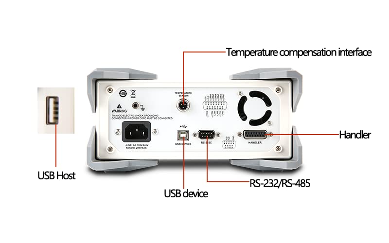
Figure 2: Rear panel connections including power input and communication interfaces.
2.3 Connecting Test Leads
The UT3513 uses a four-terminal measurement method for high accuracy. Connect the test leads to the DRIVE (H, L) and SENSE (H, L) terminals on the front panel. Ensure a secure connection for reliable measurements.

Figure 3: Front panel with test lead connection points.
2.4 Initial Power-On
Press the power button located on the front panel to turn on the instrument. The 4.3-inch LCD screen will illuminate, and the device will perform a self-test before displaying the main measurement interface.
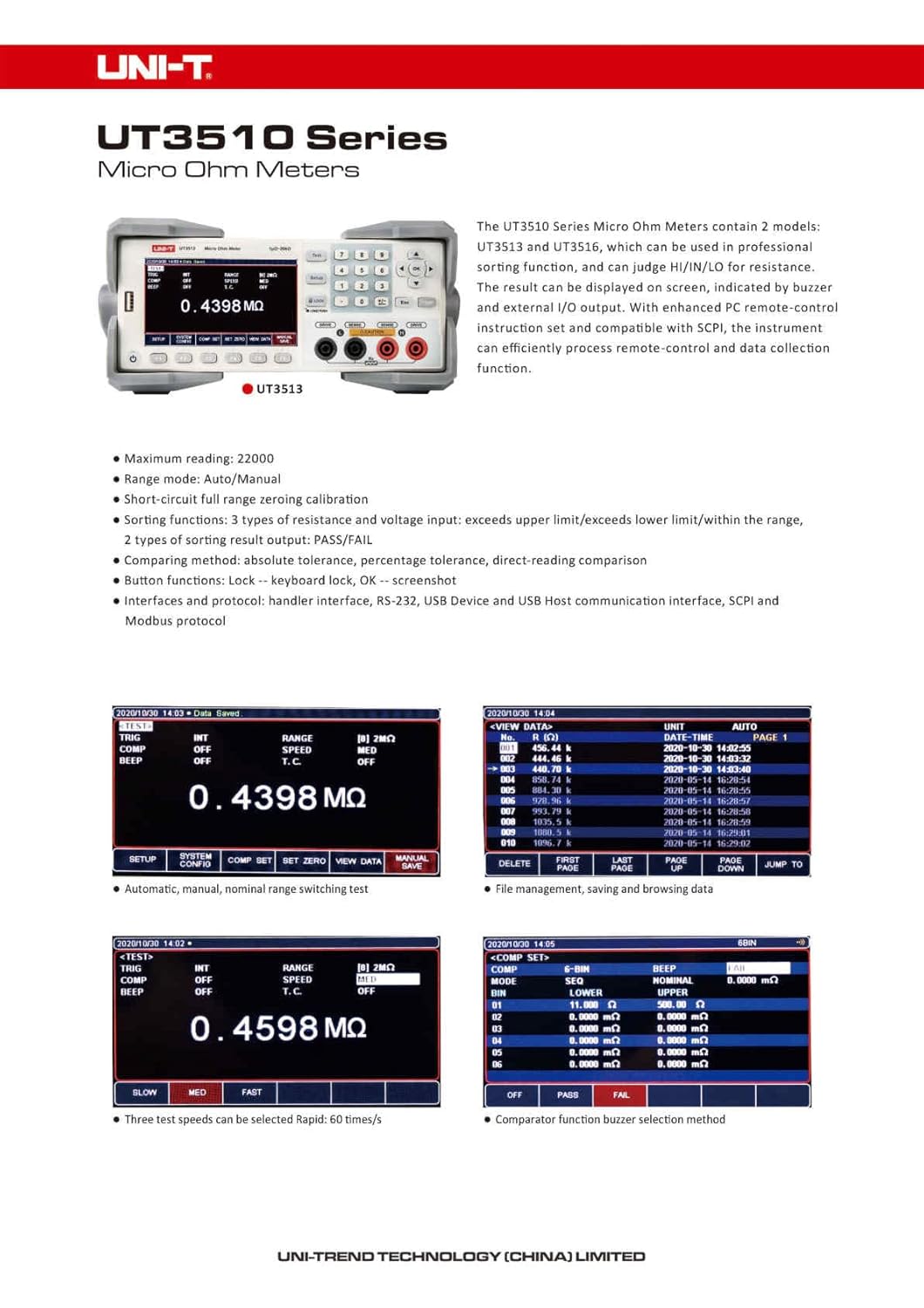
Figure 4: UT3510 Series Micro Ohm Meter with standard accessories.
3. Operating Instructions
3.1 Basic Resistance Measurement
- Ensure the test leads are correctly connected to the instrument and the component under test.
- Power on the instrument.
- Select the desired range mode (Automatic, Manual, or Nominal) using the 'RANGE' setting. Automatic mode is recommended for general use.
- Press the 'TEST' button to initiate a measurement. The resistance value will be displayed on the LCD.

Figure 5: Display interface showing measurement and settings.
3.2 Test Speed Selection
The UT3513 offers three test speeds:
- Slow: 3 times/second
- Medium: 18 times/second
- Fast: 60 times/second
Select the appropriate speed based on your measurement requirements. Faster speeds are suitable for production line testing, while slower speeds offer higher stability.

Figure 6: Test speed selection interface.
3.3 Comparator Function
The UT3513 includes one set of comparator functions to judge resistance values as HI (High), IN (In-range), or LO (Low). This is useful for sorting components. Comparison methods include direct reading comparison, absolute value tolerance, and percentage tolerance.
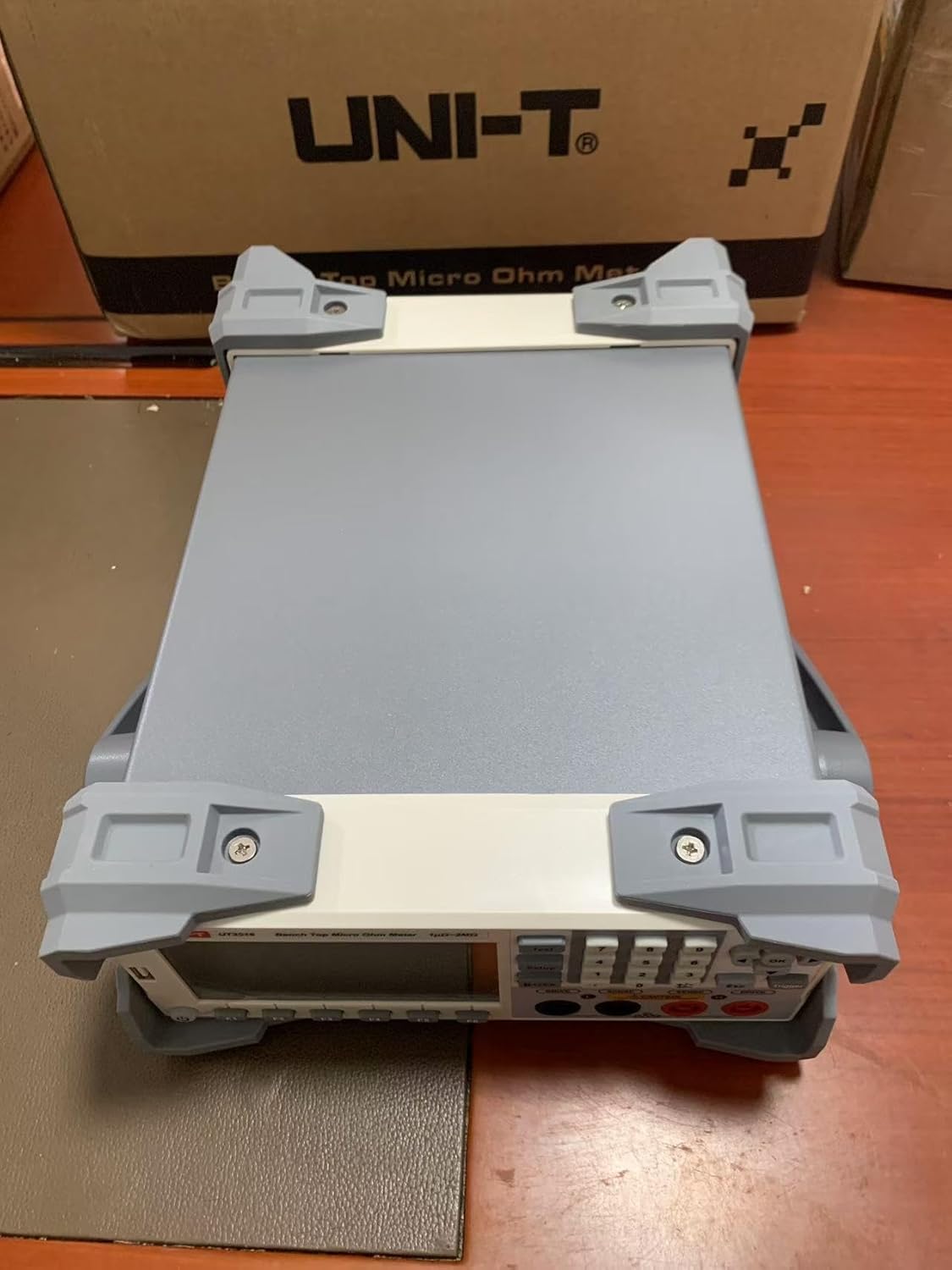
Figure 7: Comparator function settings.
3.4 File Management
The instrument allows for saving and browsing measured data. You can manually save display values and quickly review them on the screen. File management also enables saving up to 10 sets of instrument settings, which can be easily recalled when starting up or changing test specifications.

Figure 8: File management interface for saving and browsing data.
3.5 PC Connectivity
The UT3513 features RS-232/RS-485 and USB Device interfaces. It supports SCPI and Modbus RTU protocols for communication with computers, PLCs, or WINCE devices. This allows for remote control and efficient data acquisition.
4. Maintenance
4.1 Cleaning
To clean the instrument, use a soft, dry cloth. For stubborn dirt, a cloth lightly dampened with water or a mild detergent may be used. Do not use abrasive cleaners, solvents, or immerse the instrument in water.
4.2 Battery Information
The UT3513 requires 1 Lithium Metal battery (included). Refer to the battery compartment for replacement instructions if necessary. Ensure proper polarity when replacing batteries.
4.3 Storage
When not in use for extended periods, store the instrument in a dry, dust-free environment away from direct sunlight and extreme temperatures. Disconnect the power cord and remove batteries if storing for very long durations.
5. Troubleshooting
If the instrument does not function as expected, consider the following basic troubleshooting steps:
- No Power: Check the power cord connection to both the instrument and the AC outlet. Ensure the power switch is in the 'ON' position.
- Incorrect Readings: Verify that the test leads are securely connected to both the instrument and the component. Ensure the component is clean and free of oxidation. Check the selected range mode.
- Communication Issues: For PC connectivity, ensure the correct drivers are installed and the communication settings (baud rate, parity, etc.) match between the instrument and the computer.
For persistent issues, consult the full product manual or contact Uni-Trend customer support.
6. Specifications (UT3513)
| Feature | Specification |
|---|---|
| Resistance Range | 1µΩ ~ 20kΩ |
| Basic Accuracy | 0.05% |
| Max. Reading | 20000 counts |
| Range Mode | Automatic, Manual, Nominal |
| Test Speed | Slow (3/s), Medium (18/s), Fast (60/s) |
| Display | 4.3 inch LCD |
| Interfaces | RS-232/RS-485, USB Device, USB Host |
| Power Supply | AC 100-240V, 50/60Hz |
| Product Dimensions (L x W x H) | 16.5 x 11 x 12 cm |
| Product Weight | 2 kg |
| Certifications | CE, ISO 9001, RoHS, UKCA |
Figure 9: Technical Specifications for UT3513 and UT3516.
7. Warranty and Support
7.1 Warranty Information
For detailed warranty information, please refer to the warranty card included with your product or contact your point of purchase. Warranty terms typically cover manufacturing defects for a specified period.
7.2 Customer Support
For technical assistance, service, or inquiries, please contact Uni-Trend customer support or visit their official website. You can find more information at www.uni-trend.com.

Figure 10: Uni-Trend contact information.