UNI-T HY-UT572
UNI-T UT572 Advance Earth Resistance Tester User Manual
Model: HY-UT572
1. Introduction
The UNI-T UT572 is an advanced earth resistance tester designed for precise measurement of earth resistance and soil resistivity. This instrument is suitable for various on-site applications, including power equipment wiring and lightning protection equipment. It features 2/3/4-wire measurement capabilities, selectable test frequencies, and data storage functions, making it a versatile tool for electrical testing professionals.
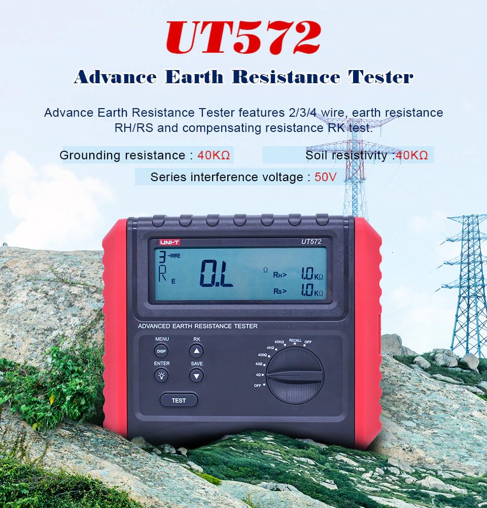
Figure 1.1: The UNI-T UT572 Advance Earth Resistance Tester, highlighting its key features and display.
2. Safety Information
Always adhere to safety precautions when operating the UT572 to prevent electric shock, injury, or damage to the instrument. This device is designed for specific electrical measurements and should not be used for testing commercial power supply voltages.
- WARNING: To avoid electrical shock, remove all test leads from the instrument before opening the battery compartment or any other case parts.
- Do not apply voltage between the testing ports of the instrument while performing grounding resistance or soil resistivity testing.
- Ensure all connections are secure and correct before initiating any test.
- Always use the specified batteries (8 x 1.5V LR6) and replace them as indicated.
- Operate the instrument within its specified measurement categories (CAT III 600V).
- If the interference voltage alarm activates, stop the measurement as the voltage is too large for safe operation.
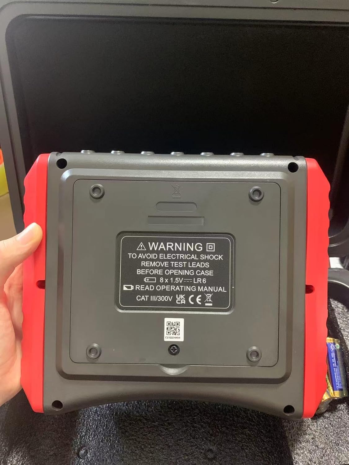
Figure 2.1: Rear view of the UT572, showing the battery compartment and safety warning label.
3. Package Contents
Verify that all items listed below are present in your package:
- UT572 Earth Resistance Tester Unit
- Simple test leads with alligator clips (double plugs x 1, single plug x 1)
- Earth spike x 4
- Standard test leads with alligator clips (40m red x 1, 20m red x 1, 20m black x 1, 10m yellow x 1, 5m green x 1)
- Elastic strap
- 1.5V battery (LR6) x 8 (included)
- Gift box / Carrying bag / Toolbox
- English Manual
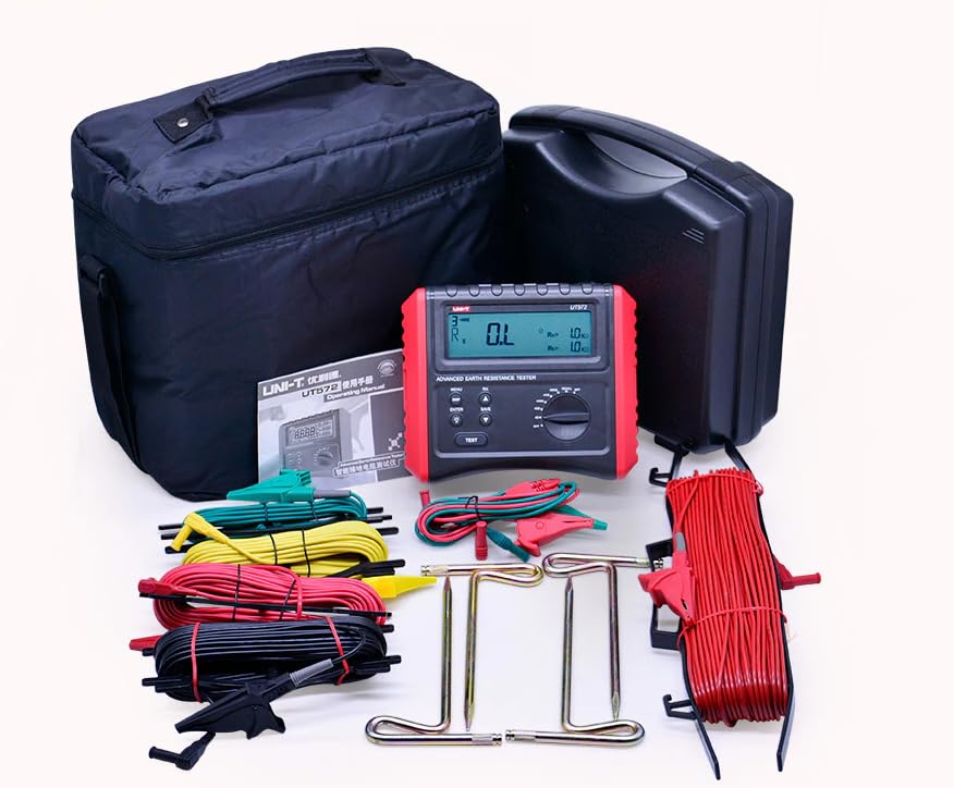
Figure 3.1: Complete package contents of the UT572, showing the meter, various test leads, earth spikes, and carrying cases.
4. Product Overview
The UT572 features a robust design suitable for field use. Key components include:
- Large 4-digit LCD Display: Provides clear readings and indications.
- Control Panel: Includes buttons for MENU, DISP, ENTER, SAVE, and a rotary switch for selecting measurement ranges and functions.
- Test Button: Initiates the measurement process.
- Input Terminals: Clearly labeled ports for connecting test leads (H, S, ES, E).

Figure 4.1: Front view of the UT572, showing the LCD display, control buttons, and rotary switch.
5. Setup
5.1 Battery Installation
The UT572 requires 8 x 1.5V LR6 (AA) batteries. To install or replace batteries:
- Ensure the instrument is powered off and all test leads are disconnected.
- Locate the battery compartment on the back of the unit.
- Open the battery compartment cover.
- Insert the 8 LR6 batteries, observing correct polarity (+/-).
- Close the battery compartment cover securely.
5.2 Connecting Test Leads
Connect the appropriate test leads to the input terminals (H, S, ES, E) based on the type of measurement you intend to perform (2-wire, 3-wire, 4-wire, or soil resistivity). Refer to the operating instructions for specific connection diagrams.
6. Operating Instructions
6.1 General Operation
- Power On/Off: Rotate the function switch to any measurement range to power on. Rotate to "OFF" to power off.
- LCD Backlight: Press the backlight button (light bulb icon) to turn the display backlight on or off.
- Data Hold: Press the "HOLD" button to freeze the current reading on the display. Press again to release.
- Auto Power Off: The instrument will automatically power off after a period of inactivity to conserve battery life.
6.2 Earth Resistance Measurement
The UT572 supports 2-wire, 3-wire, and 4-wire earth resistance measurements.
6.2.1 Precision (3-wire) Testing
This method is commonly used for general earth resistance measurements.
- Connect the test leads as shown in Figure 6.1. The E terminal connects to the grounding terminal to be measured. The S and H terminals connect to auxiliary grounding pins placed at specific distances (typically 5-10m) from the grounding terminal.
- Select the appropriate earth resistance range using the rotary switch.
- Press the "TEST" button to initiate the measurement.
- Read the earth resistance value from the LCD.
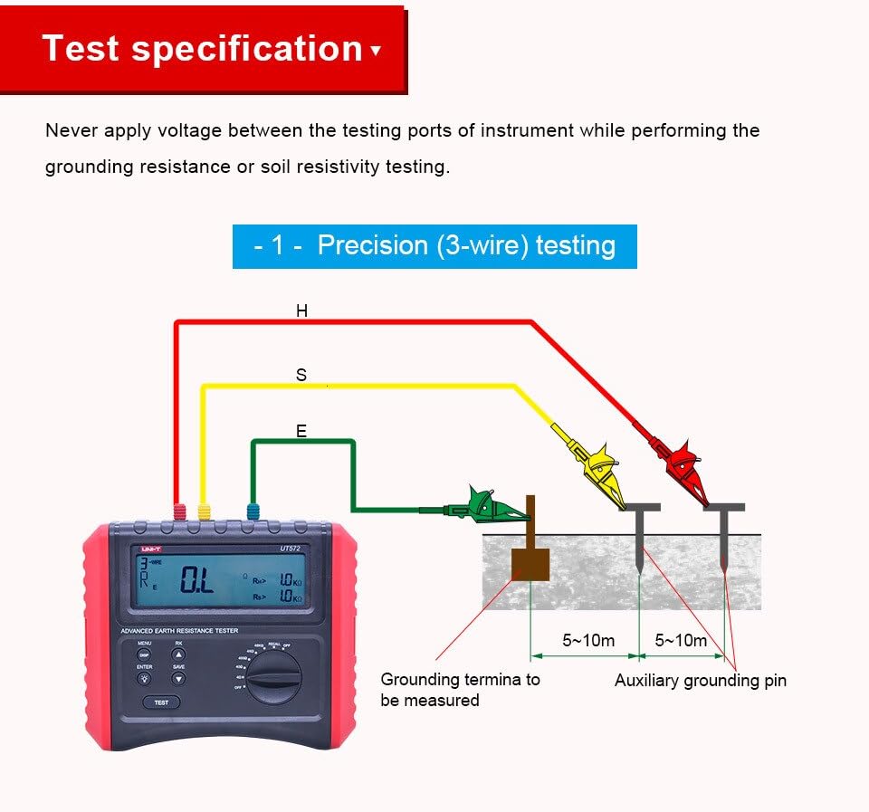
Figure 6.1: Connection diagram for 3-wire earth resistance testing.
6.2.2 Precision (4-wire) Testing
The 4-wire method provides the most accurate measurement by eliminating the resistance of the test leads.
- Connect the test leads as shown in Figure 6.2. The E and ES terminals connect to the grounding terminal. The S and H terminals connect to auxiliary grounding pins.
- Select the appropriate earth resistance range.
- Press the "TEST" button.
- Read the earth resistance value.
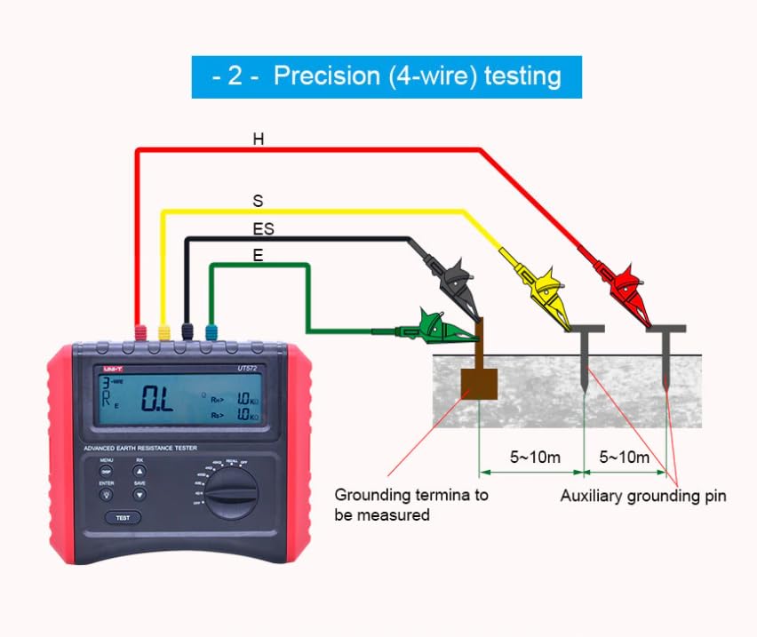
Figure 6.2: Connection diagram for 4-wire earth resistance testing.
6.2.3 Simple (2-wire) Testing
This method is suitable for quick checks where high precision is not critical, or when auxiliary earth spikes cannot be used.
- Connect the test leads as shown in Figure 6.3. The E terminal connects to the grounding terminal, and the S terminal connects to a known good earth point (e.g., water pipe, building ground).
- Select the appropriate earth resistance range.
- Press the "TEST" button.
- Read the earth resistance value.

Figure 6.3: Connection diagram for 2-wire earth resistance testing. Note: The instrument cannot be used to test the voltage of commercial power supply.
6.3 Soil Resistivity Testing
The UT572 can measure soil resistivity using the Wenner method.
- Place four earth spikes in a straight line at equal distances (a) from each other, as shown in Figure 6.4.
- Connect the test leads: H to the outermost spike, S to the inner spike, ES to the other inner spike, and E to the other outermost spike.
- Select the soil resistivity function on the rotary switch.
- Press the "TEST" button.
- The instrument will display the soil resistivity value.
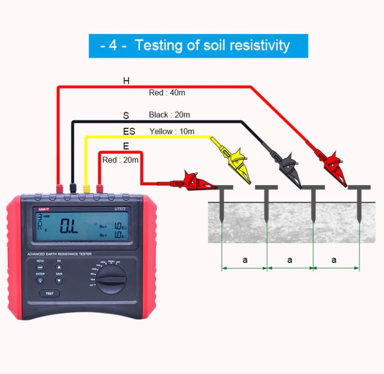
Figure 6.4: Connection diagram for soil resistivity testing using four earth spikes.
6.4 Data Storage and Recall
The UT572 can store up to 20 sets of measurement data.
- Saving Data: After a measurement, press the "SAVE" button to store the current reading.
- Recalling Data: Use the "RECALL" function (often combined with the rotary switch or a dedicated button) to browse stored data.
7. Maintenance
Proper maintenance ensures the longevity and accuracy of your UT572.
- Cleaning: Wipe the instrument with a damp cloth. Do not use abrasive cleaners or solvents.
- Battery Replacement: Replace batteries when the low battery indicator appears on the LCD. Always use new batteries of the specified type.
- Storage: Store the instrument in a cool, dry place away from direct sunlight and extreme temperatures. If storing for extended periods, remove the batteries to prevent leakage.
- Calibration: Regular calibration by qualified personnel is recommended to maintain measurement accuracy.
8. Troubleshooting
This section addresses common issues you might encounter with the UT572.
| Problem | Possible Cause | Solution |
|---|---|---|
| Instrument does not power on. | Dead or incorrectly installed batteries. | Check battery polarity and replace with new batteries if necessary. |
| "OL" (Overload) displayed. | Measurement exceeds selected range; open circuit in test leads or connections. | Select a higher range; check test lead connections and integrity. |
| Unstable or fluctuating readings. | Poor contact with earth spikes; high interference voltage; dry soil conditions. | Ensure good contact with spikes; check for external electrical interference; moisten soil if too dry. |
| Interference voltage alarm activates. | External voltage is too high for safe measurement. | Stop measurement immediately. Identify and mitigate the source of interference before re-testing. |
| Low battery indication. | Batteries are low. | Replace all batteries with new ones. |
9. Specifications
Detailed technical specifications for the UNI-T UT572 Earth Resistance Tester:
| Specification | Value |
|---|---|
| Model Number | HY-UT572 |
| Certifications | CE, UKCA |
| Earth Resistance (Re) Range | 4Ω, 40Ω, 400Ω, 4kΩ, 40kΩ |
| Earth Resistance Accuracy | ±(3%+15) for 4Ω; ±(3%+5) for others |
| Soil Resistivity (ρ) Range | 4Ω, 40Ω, 400Ω, 4kΩ, 40kΩ |
| Soil Resistivity Accuracy | ±(3%+15) for 4Ω; ±(3%+5) for others |
| Disturbance Voltage (Ust) | 50V (DC voltage/40Hz~500Hz) |
| Disturbance Frequency (Fst) | 40Hz~500Hz |
| Data Storage | 20 sets |
| Category Ratings | CAT III 600V |
| Display | 125 x 37mm LCD |
| Product Dimensions | 210 x 175 x 90 mm (6.5 x 4.33 x 4.72 inches) |
| Product Net Weight | 1.1 kg (1.32 Pounds) |
| Power Source | Battery Powered (8 x 1.5V LR6 included) |
| Test Frequencies | 94Hz/128Hz (selectable) |
| Sampling Time | 5 seconds |
| Low Battery Indication | ≤9.5V |

Figure 9.1: A detailed table of the UT572's specifications, including ranges and accuracy.
10. Warranty and Support
UNI-T products are manufactured to high quality standards and are warranted against defects in materials and workmanship. For specific warranty terms, technical support, or service inquiries, please refer to the warranty card included with your product or visit the official UNI-T website. Keep your purchase receipt as proof of purchase for warranty claims.
For further assistance, you may contact UNI-T customer support through their official channels. Information regarding support can typically be found on the manufacturer's website or in the product packaging.
Related Documents - HY-UT572
 |
UNI-T UT276A/278A Clamp Earth Ground Testers Operating Manual Comprehensive operating manual for UNI-T UT276A and UT278A clamp-on ground resistance testers. Covers safety instructions, product overview, specifications, clamp meter structure, LCD display, operation methods, measurement principles, on-site applications, and notes on ground resistance measurement. |
 |
UNI-T UT276A+ & UT278A+ Clamp Earth Ground Testers Operating Manual Comprehensive operating manual for UNI-T UT276A+ and UT278A+ clamp earth ground testers. Covers technical specifications, measurement principles, operation methods, field applications, and safety precautions for accurate grounding resistance testing. |
 |
UNI-T UT276A+ & UT278A+ Clamp Earth Ground Testers Operating Manual Comprehensive operating manual for UNI-T UT276A+ and UT278A+ Clamp Earth Ground Testers, detailing their features, specifications, operation methods, safety precautions, and field applications for accurate ground resistance testing. |
 |
UNI-T UT8802E Digital Multimeter User Manual Comprehensive user manual for the UNI-T UT8802E digital multimeter, detailing its features, specifications, safety precautions, and step-by-step instructions for various electrical measurements including voltage, current, resistance, capacitance, frequency, continuity, diodes, transistors, and thyristors. |
 |
UNI-T UT273+/UT275+ Clamp Earth Resistance Tester User Manual User manual for the UNI-T UT273+ and UT275+ Clamp Earth Resistance Testers, detailing operational principles, included accessories, and important disclaimers for accurate earthing resistance measurements. |
 |
UNI-T UT276A+ and UT278A+ Clamp Earth Ground Testers Operating Manual This operating manual provides detailed information on the UNI-T UT276A+ and UT278A+ Clamp Earth Ground Testers, covering their features, technical specifications, operation methods, field applications, and packing list. |
Ask a question about this manual
Ask about setup, troubleshooting, compatibility, parts, safety, or missing instructions. Manuals+ will review the question and use this page’s manual context to help answer it.