1. Introduction
The UNI-T UT582+ Digital RCD (ELCB) Tester is a professional instrument designed for testing Residual Current Devices (RCDs) and Earth Leakage Circuit Breakers (ELCBs). It is primarily used to verify the proper functioning and tripping characteristics of RCDs in electrical circuits, ensuring safety against electrical shocks. This device is suitable for single-phase circuits with a supply voltage range of 195V~253V and a voltage measurement range of 30V~600V, 45Hz~65Hz. It features an AUTO RAMP function, disconnect buzzer, over-range display, and mis-operation buzzer for enhanced user experience and safety.

Figure 1.1: Front view of the UNI-T UT582+ Digital RCD (ELCB) Tester.
2. Safety Information
Always adhere to local electrical safety regulations and standards when using this device. Failure to do so may result in electric shock, injury, or damage to the instrument. This device is intended for use by qualified personnel only.
- DO NOT use the tester if it appears damaged or is operating abnormally.
- DO NOT exceed the maximum input ratings specified in the technical specifications.
- Ensure proper connection of test leads before performing any test.
- Always disconnect the test leads from the circuit before changing functions or turning off the device.
- The device is designed for single-phase circuits within the specified voltage range.
- Refer to the "WIRING CHECK" section on the back of the device for correct lead connections.
3. Product Overview
The UT582+ features a clear LCD display, intuitive controls, and robust construction for reliable performance. Understanding its components is crucial for effective operation.
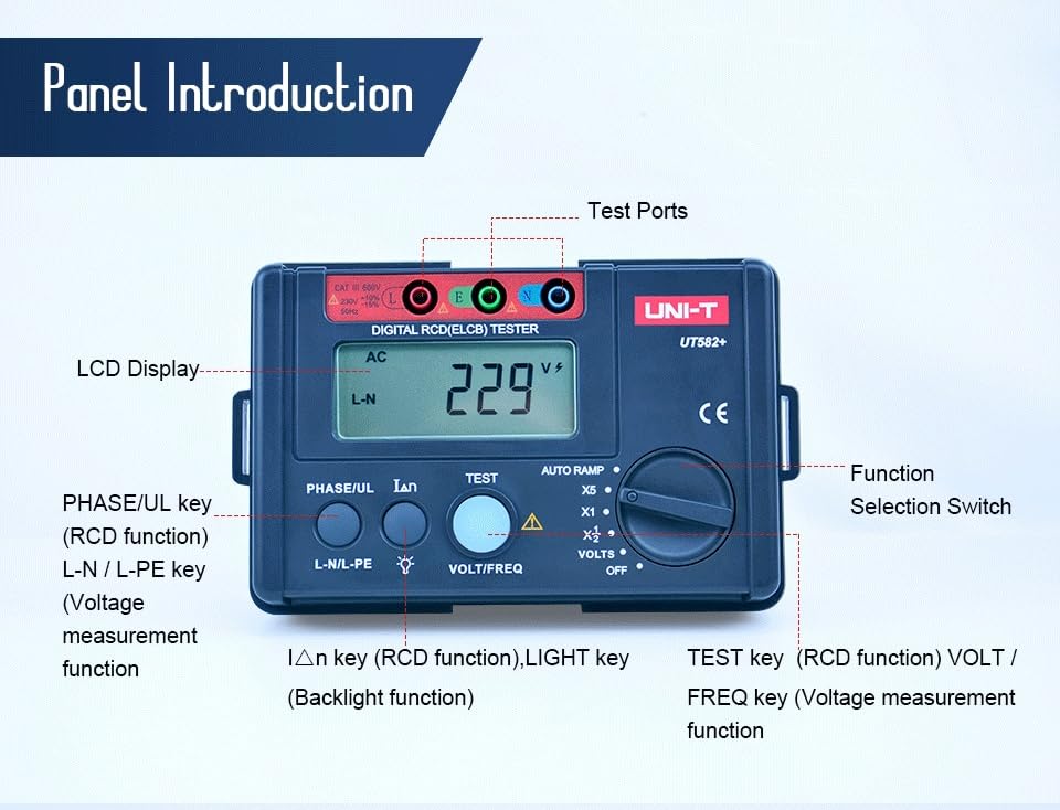
Figure 3.1: Labeled diagram of the UT582+ front panel and test ports.
Key Components:
- LCD Display: Shows measurement readings, selected functions, and indicators.
- Test Ports: Connections for the three-terminal test lead (L, N, PE).
- Function Selection Switch: Rotary switch to select RCD test current (X1/2, X1, X5, AUTO RAMP) or voltage measurement (VOLTS, OFF).
- PHASE/UL Key: Used for RCD function and selecting phase.
- L-N/L-PE Key: Used for voltage measurement function, switching between L-N and L-PE voltage display.
- IΔn Key (RCD function) / LIGHT Key (Backlight function): Toggles RCD current settings or activates the LCD backlight.
- TEST Key (RCD function) / VOLT/FREQ Key (Voltage measurement function): Initiates an RCD test or switches between voltage and frequency display during voltage measurement.

Figure 3.2: Rear view of the UT582+ with wiring check instructions.
4. Setup
4.1 Unpacking and Inspection
Upon receiving your UT582+ tester, carefully unpack all components and inspect for any signs of damage. The standard accessories include test leads, an elastic strap, and this English manual.

Figure 4.1: The UT582+ tester as packaged in its retail box.
4.2 Battery Installation
The UT582+ is powered by 6 x 1.5V AA alkaline batteries. To install or replace batteries:
- Ensure the device is turned OFF.
- Locate the battery compartment on the rear of the unit.
- Unscrew the battery cover and remove it.
- Insert 6 AA batteries, observing the correct polarity (+/-) as indicated inside the compartment.
- Replace the battery cover and secure it with the screw.

Figure 4.2: The UT582+ tester with its included carrying case and test leads.
4.3 Connecting Test Leads
Connect the three-terminal test lead to the corresponding ports on the tester (L, N, PE). Ensure a secure connection. The other end of the test lead, typically a standard plug, will be connected to the circuit under test.
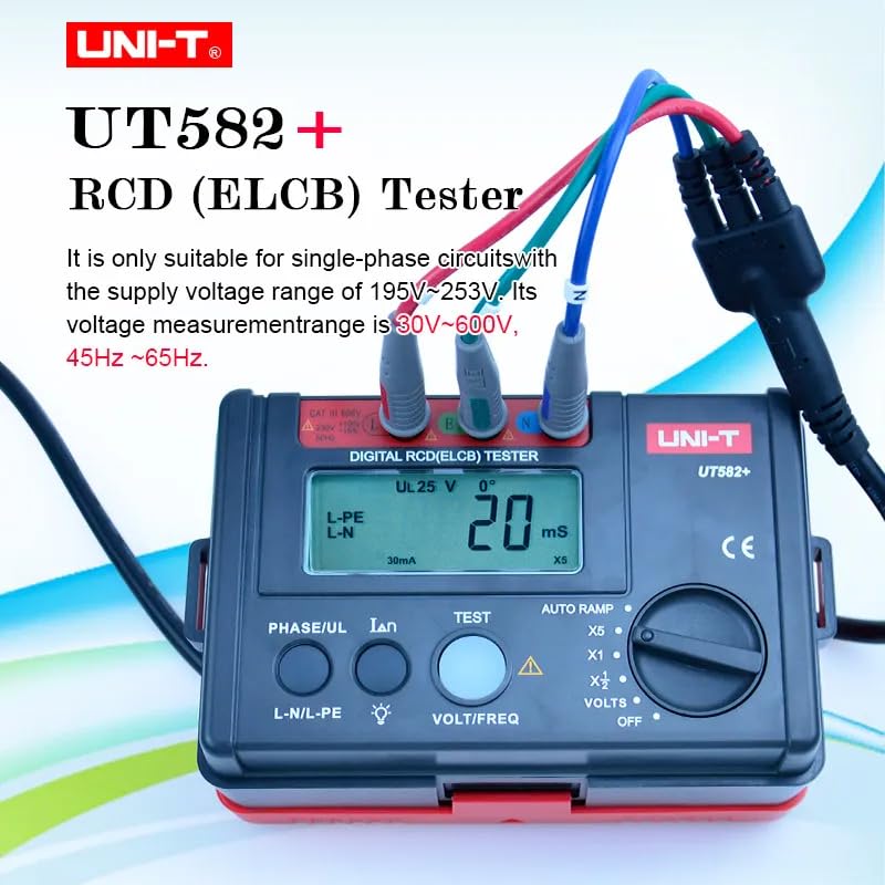
Figure 4.3: The UT582+ with its three-terminal test lead connected, ready for use.
5. Operating Instructions
5.1 Powering On/Off
Turn the Function Selection Switch to any desired function (e.g., VOLTS, X1) to power on the device. To power off, turn the switch to the "OFF" position. The device also features an auto-off function to conserve battery life.
5.2 Voltage Measurement
To measure voltage:
- Turn the Function Selection Switch to "VOLTS".
- Connect the test leads to the circuit.
- The LCD will display the L-N voltage by default. Press the L-N/L-PE key to switch between L-N and L-PE voltage readings.
- Press the VOLT/FREQ key to toggle between voltage and frequency display.
- The display range for voltage is 30V~600V. "----" indicates no input or extremely small input. "<30V" indicates input less than 30V. ">600V" indicates input greater than 600V.

Figure 5.1: L-N Voltage Measurement in progress.
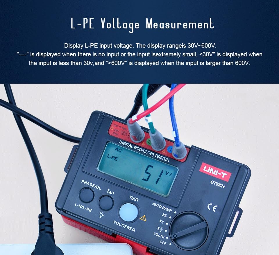
Figure 5.2: L-PE Voltage Measurement in progress.
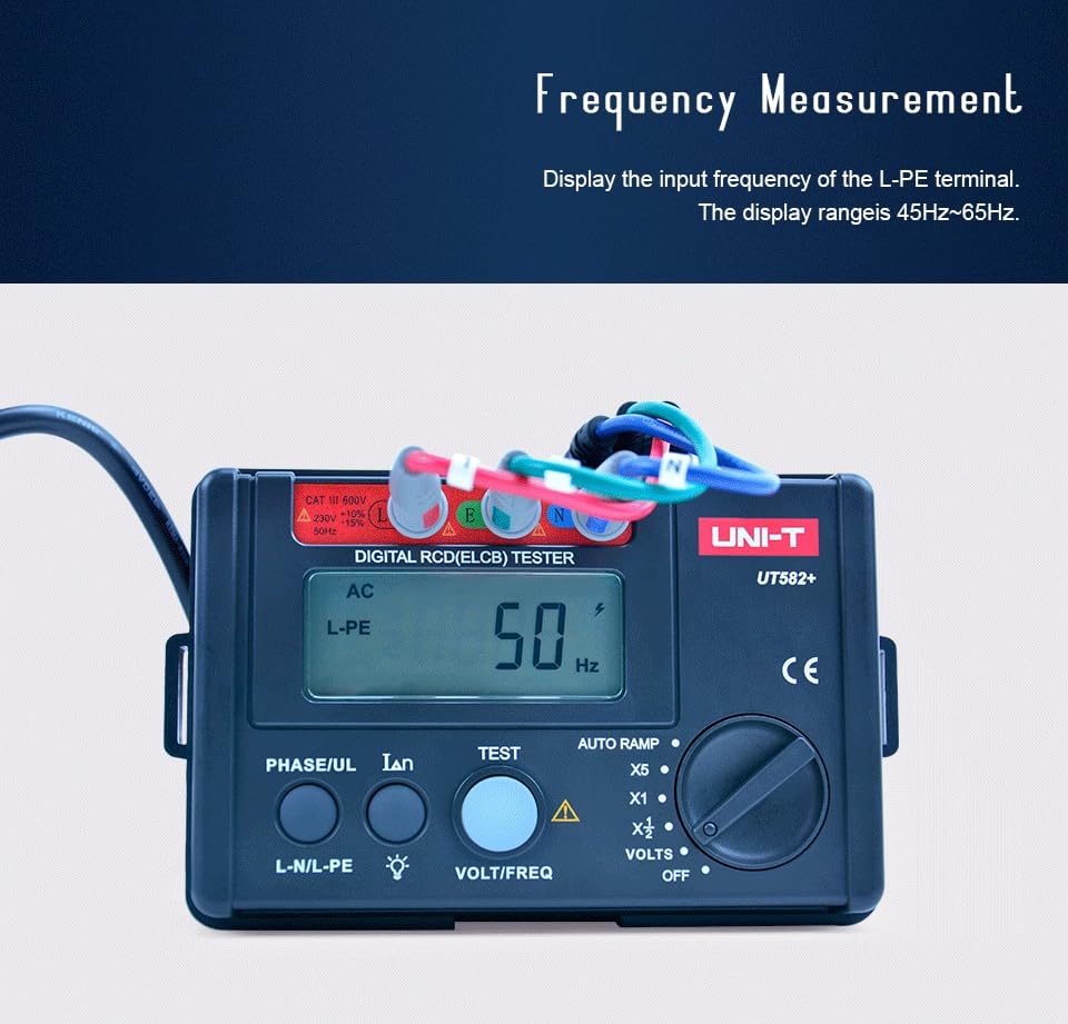
Figure 5.3: Frequency Measurement display.
5.3 RCD (ELCB) Testing
The UT582+ allows for various RCD tests, including standard trip current tests and AUTO RAMP tests.
Standard RCD Test:
- Turn the Function Selection Switch to the desired RCD current setting (X1/2, X1, X5).
- Connect the test leads to the circuit.
- Press the IΔn key to select the nominal residual operating current (e.g., 10mA, 30mA, 100mA, 300mA, 500mA).
- Press the PHASE/UL key to select the phase angle (0° or 180°).
- Press the TEST key to initiate the RCD test. The device will measure the trip time.
AUTO RAMP Test:
The AUTO RAMP function gradually increases the test current until the RCD trips, allowing for precise determination of the actual tripping current.
- Turn the Function Selection Switch to "AUTO RAMP".
- Connect the test leads to the circuit.
- Press the IΔn key to select the nominal residual operating current.
- Press the PHASE/UL key to select the phase angle (0° or 180°).
- Press the TEST key to initiate the AUTO RAMP test. The device will display the tripping current.
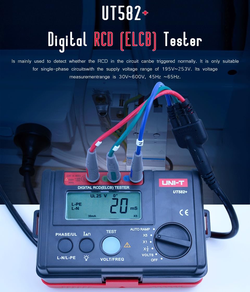
Figure 5.4: The UT582+ in use, testing an RCD in an electrical panel.
5.4 Video Demonstration
Watch this official video for a visual guide on the features and operation of the UNI-T UT582+ Digital RCD (ELCB) Tester.
Video 5.1: Official demonstration of the UNI-T UT582+ Digital RCD (ELCB) Tester, covering its appearance, test lead connection, upgrade functions (voltage measurement, auto-off, backlight, battery power), and key features like phase angle selection, contact voltage alarm, and auto ramp test. It also highlights applications in production, installation, inspection, and maintenance.
6. Maintenance
Proper maintenance ensures the longevity and accuracy of your UT582+ tester.
- Cleaning: Wipe the device with a dry, soft cloth. Do not use abrasive cleaners or solvents.
- Storage: Store the device in a cool, dry place away from direct sunlight and extreme temperatures. If storing for extended periods, remove the batteries to prevent leakage.
- Battery Replacement: Replace batteries when the low battery indicator appears on the LCD.
- Calibration: For professional use, periodic calibration by a qualified service center is recommended to maintain accuracy.
7. Troubleshooting
This section addresses common issues you might encounter with your UT582+ tester.
| Problem | Possible Cause | Solution |
|---|---|---|
| Device does not power on. | Dead or incorrectly installed batteries. | Check battery polarity and replace batteries if necessary. |
| Inaccurate readings. | Poor test lead connection; device needs calibration. | Ensure test leads are securely connected. Consider professional calibration. |
| RCD does not trip during test. | Incorrect test settings; faulty RCD; circuit issues. | Verify test current and phase angle settings. Inspect the RCD and circuit wiring. Consult a qualified electrician. |
| "OL" displayed. | Over-range condition. | The measured value exceeds the device's range for the selected function. Disconnect immediately. |
8. Specifications
Detailed technical specifications for the UNI-T UT582+ Digital RCD (ELCB) Tester.

Figure 8.1: Detailed specifications table for the UT582+.
| Characteristic | Value |
|---|---|
| Model | HY-UT582+ |
| Certifications | CE, UKCA |
| Rated Operating Current | 10mA/20mA/30mA/100mA/300mA/500mA |
| Trip Time Accuracy | ±(2%+2) |
| Operating Voltage (Freq.) | 195V~253V |
| Voltage Measurement Range | 30V~600V |
| Frequency Range | 45Hz~65Hz |
| Power Source | 6 x 1.5V AA alkaline batteries (included) |
| Product Dimensions | 160 x 100 x 71mm (6.5 x 4.33 x 4.72 inches) |
| Product Net Weight | 400g (1.32 Pounds) |
| Safety Rating | CAT III 600V |
9. Warranty and Support
UNI-T products are designed and manufactured to the highest quality standards. For warranty information and technical support, please refer to the official UNI-T website or contact your local distributor. Keep your purchase receipt as proof of purchase for warranty claims.
For further assistance, you may visit the UNI-T Store on Amazon.


