
Uni-Trend HY-UTL8513
UNI-T UTL8500 Series Programmable DC Electronic Load Instrument User Manual
Model: UTL8513
1. Introduction
The UNI-T UTL8500 Series is a high-performance, cost-effective programmable DC electronic load instrument designed for various testing applications. This series offers high resolution measurements and multiple protection mechanisms to ensure reliable operation. It is equipped with an RS-232 communication interface and supports various testing functions and modes, making it suitable for education, scientific research, and manufacturing environments.
The UTL8513 model, part of this series, provides specific capabilities for high-precision testing of battery capacity, internal resistance, and other DC load characteristics.

Figure 1.1: Front view of the UNI-T UTL8500 Series Electronic Load, showing the LCD screen, control panel, and input terminals.
2. Key Features
- High Resolution: 0.1mV/0.1mA for precise measurements.
- Wide Voltage/Current/Power Range:
- Voltage Test Range: 0~150V/500V
- Current Test Range: 0~15A/30A/120A
- Power Test Range: 0~150W/300W/600W
- Multiple Basic Test Modes: Constant Current (CC), Constant Voltage (CV), Constant Resistance (CR), Constant Power (CP).
- Rich Test Modes: Includes dynamic test, list test, combination test, OCP/OPP test, CR-LED test, battery test, load effect, OVP test, short circuit, and time test.
- 4.3-inch LCD Screen Display: Provides clear and comprehensive data visualization.
- Connectivity: Equipped with RS-232 communication interface for remote control and data acquisition.
- Screenshot Function: Save current screen images to a USB flash drive.
- List Call and System Upgrade: Save and recall frequently used list test files; quick system upgrades via USB flash drive.
- Multiple Protection Functions: Over voltage, low voltage, over current, over power, over heat, and anti-reverse connection protection.
- Compact Design: ½ 2U size for efficient space utilization.
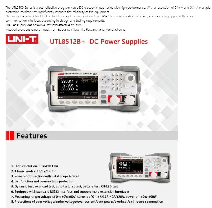
Figure 2.1: Overview of key features and capabilities of the UTL8500 series.
3. Setup
3.1 Unpacking and Inspection
Carefully unpack the instrument and inspect it for any signs of damage during transit. Verify that all accessories listed in the packing list are present. If any damage or missing items are found, contact your supplier immediately.
3.2 Rear Panel Connections
Before connecting the instrument, ensure the power switch is in the OFF position. Refer to the diagram and table below for proper connections.
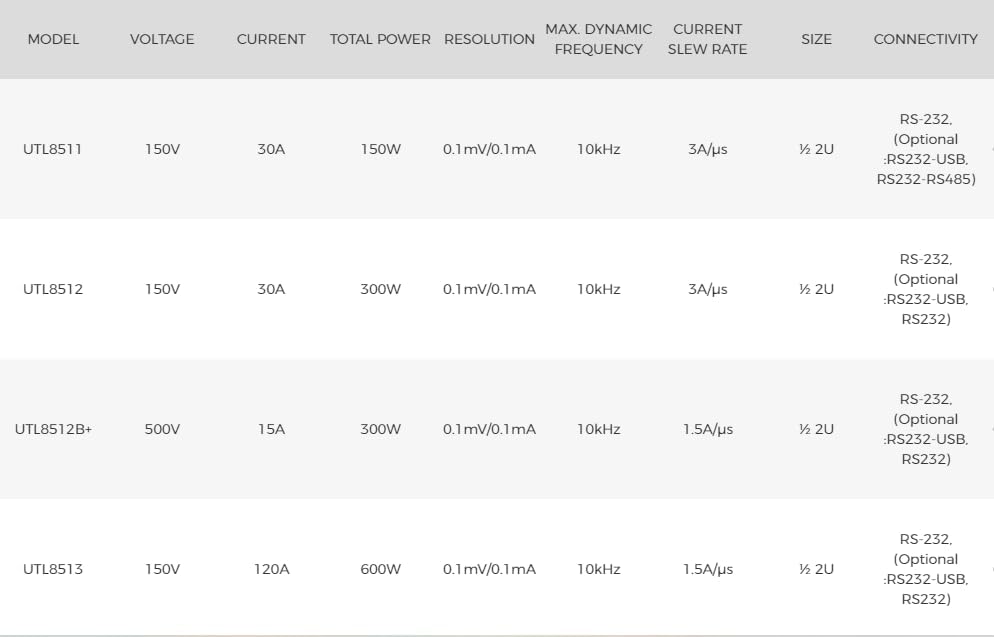
Figure 3.1: Rear Panel of the UTL8500 Series Electronic Load.
| No. | Items | Description |
|---|---|---|
| ① | AC 220/110V Socket | AC Power Input Socket (with Fuse) |
| ② | ON/OFF Power Button | Main power switch for the instrument. |
| ③ | Trigger Signal Terminal | Used for external trigger signals. Refer to part 6.2 for details. |
| ④ | AC 220/110V Transfer Switch | Voltage Scale Switch of AC Power Source. Ensure this matches your local power supply. |
| ⑤ | RS232 Interface | External Communication Interface for remote control. |
| ⑥ | Current Monitor Terminal | BNC Current Monitor Output Terminal. |
| ⑦ | Sense (Remote Compensation) Terminal | Remote Voltage Sampling for Electrical Load. |
| ⑧ | Specification of Fuse | 240V/0.25A, 120V/0.5A. Ensure correct fuse is used for your region. |
3.3 Power Connection
Connect the provided AC power cord to the AC input socket (①) on the rear panel and then to a suitable power outlet. Ensure the voltage transfer switch (④) is set correctly for your local power supply (110V or 220V).
3.4 Load Connection
Connect the device under test (DUT) to the input terminals on the front panel. For precise voltage regulation at the DUT, use the Sense (Remote Compensation) terminals (⑦) if available on your model and application.
4. Operating Instructions
4.1 Powering On/Off
Press the ON/OFF Power Button (②) on the rear panel to power on the instrument. The LCD screen will illuminate, and the system will initialize. To power off, press the button again.
4.2 Basic Test Modes (CC/CV/CR/CP)
The UTL8500 series supports four fundamental operating modes:
- Constant Current (CC): The electronic load draws a constant current regardless of the input voltage.
- Constant Voltage (CV): The electronic load maintains a constant voltage across its input terminals.
- Constant Resistance (CR): The electronic load simulates a constant resistance, drawing current proportional to the input voltage.
- Constant Power (CP): The electronic load draws a constant power, adjusting current inversely to the input voltage.
Select the desired mode using the front panel controls and set the corresponding parameters (current, voltage, resistance, or power) as required for your test.
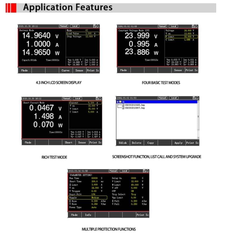
Figure 4.1: Examples of various test modes and screen displays, including Battery Mode, Constant Voltage Mode, Short Circuit Mode, and Screenshot Function.
4.3 Advanced Test Modes
Beyond the basic modes, the UTL8500 series offers specialized test functions:
- Dynamic Test: For simulating transient load changes.
- List Test: Program a sequence of steps with varying load parameters.
- Combination Test: Combine different test modes.
- OCP/OPP Test: Over Current Protection / Over Power Protection testing.
- CR-LED Test: Specific mode for LED driver testing.
- Battery Test: For battery discharge and capacity testing.
- Load Effect: Evaluate the impact of load changes.
- OVP Test: Over Voltage Protection testing.
- Short Circuit: Simulate short circuit conditions.
- Time Test: Conduct tests over a specified duration.
Consult the detailed user manual (not this summary) for specific instructions on configuring and executing these advanced test modes.
4.4 Screenshot and Data Management
The instrument allows you to capture the current screen display by pressing the [Screenshot] button. Images are saved to a connected USB flash drive. You can also save and recall frequently used list test files from Flash memory or a USB flash drive for convenience.
5. Maintenance
Proper maintenance ensures the longevity and accuracy of your UTL8500 series electronic load.
- Cleaning: Use a soft, dry cloth to clean the exterior of the instrument. For stubborn dirt, a cloth lightly dampened with water or a mild detergent can be used. Do not use abrasive cleaners or solvents. Ensure no liquid enters the instrument.
- Ventilation: Ensure the ventilation openings on the instrument are clear and unobstructed to prevent overheating.
- Storage: When not in use for extended periods, store the instrument in a clean, dry environment, away from direct sunlight, extreme temperatures, and high humidity.
- Fuse Replacement: If the instrument does not power on, check the fuse located in the AC input socket (①). Replace it only with a fuse of the correct rating (240V/0.25A or 120V/0.5A) as specified on the rear panel and in Table 3.1.
6. Troubleshooting
This section provides solutions to common issues. For problems not listed here, contact technical support.
- Instrument does not power on:
- Check if the power cord is securely connected to both the instrument and the power outlet.
- Verify that the power outlet is functional.
- Inspect the fuse in the AC input socket and replace if blown (refer to Maintenance section for fuse specifications).
- Ensure the AC 220/110V Transfer Switch (④) is set correctly for your region's voltage.
- No load current/voltage reading:
- Ensure the load is properly connected to the input terminals.
- Check the test mode settings and parameters to ensure they are configured correctly for your application.
- Verify that the DUT is supplying power.
- Over-protection error message:
- The instrument has triggered one of its protection mechanisms (e.g., over voltage, over current, over power, over heat).
- Check the input voltage, current, and power from the DUT to ensure they are within the instrument's specified limits.
- Allow the instrument to cool down if an over-heat protection is indicated.
- Adjust test parameters to stay within safe operating limits.
- Communication issues via RS-232:
- Ensure the RS-232 cable is securely connected to both the instrument and the computer.
- Verify the communication settings (baud rate, data bits, stop bits, parity) on both the instrument and the computer match.
- Check if the correct COM port is selected on the computer.
- Ensure the necessary drivers are installed on the computer.
7. Specifications (UTL8513 Model)
The following table provides detailed specifications for the UTL8513 model. Note that specifications may vary slightly between models in the UTL8500 series.

Figure 7.1: Comparative specifications for UTL8511, UTL8512, UTL8512B+, and UTL8513 models.
| Parameter | Value (UTL8513) |
|---|---|
| Voltage Range | 0-150V |
| Current Range | 0-120A |
| Total Power | 600W |
| Resolution | 0.1mV/0.1mA |
| Max. Dynamic Frequency | 10kHz |
| Current Slew Rate | 1.5A/µs |
| Size | ½ 2U |
| Connectivity | RS-232 (Optional: RS232-USB, RS232-RS485) |
| Product Dimensions | 16.5 x 11 x 12 cm |
| Item Weight | 2 Kilograms |
| Power Source | Battery Powered (Internal Lithium Metal battery included) |
| Operating Temperature | 0-40°C |
| Safety Compliance | CE, UKCA, ISO 9001, RoHS |
8. Warranty and Support
UNI-Trend provides a standard warranty for its products. Please refer to the warranty card included with your purchase or visit the official UNI-T website for detailed warranty terms and conditions specific to your region.
For technical support, service, or inquiries regarding your UTL8513 electronic load, please contact UNI-Trend customer service or your local distributor. Contact information can typically be found on the UNI-T website or in the product packaging.
When contacting support, please have your model number (UTL8513) and serial number ready.
Ask a question about this manual
Ask about setup, troubleshooting, compatibility, parts, safety, or missing instructions. Manuals+ will review the question and use this page’s manual context to help answer it.