Introduction
This manual provides detailed instructions for the installation, operation, and maintenance of your Diyeeni B75 MS Mini ITX Motherboard. Please read this manual thoroughly before proceeding with installation to ensure proper setup and functionality.
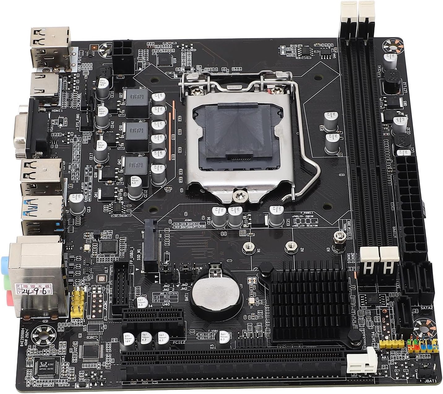
Image: Top-down view of the Diyeeni B75 MS Mini ITX Motherboard, highlighting the CPU socket, RAM slots, and various connectors.
Safety Information
- Always disconnect power from your computer before installing or removing any components.
- Wear an anti-static wrist strap to prevent electrostatic discharge (ESD) damage to components.
- Handle the motherboard by its edges to avoid touching sensitive components.
- Ensure proper ventilation within your computer case to prevent overheating.
Package Contents
Verify that all items are present in the package:
- 1 x Diyeeni B75 MS Motherboard
- 1 x Connection Cable (SATA cable)
- 1 x Metal Plate (I/O Shield)
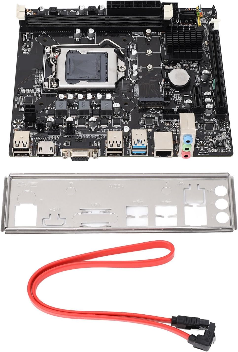
Image: The Diyeeni B75 MS Motherboard displayed alongside its included accessories, a red SATA data cable, and a silver I/O shield.
Specifications
| Feature | Detail |
|---|---|
| Motherboard Model | B75 MS |
| Board Type | ITX |
| CPU Socket Type | LGA 1155 |
| Compatible Processors | Intel Pentium, Intel Core i3/i5 (2nd and 3rd Generation) |
| Chipset Type | Intel B75 Express |
| Memory Slots | 2 x DDR3 DIMM |
| Memory Capacity Peak | 16GB |
| Memory Clock Speed | 1066/1333/1600/1866 MHz |
| SATA Interface | 1 x SATA3.0, 3 x SATA2.0 |
| Graphics Card Slot | 1 x PCI E 16X |
| USB Interface | 4 x USB3.0 (2 rear, 2 via internal header), 6 x USB2.0 (2 rear, 4 via internal headers) |
| Video Output | 1 x VGA, 1 x HDMI |
| Expansion Interface | NVME M.2, M.2 (for WiFi/BT or additional M.2) |
| Network Card | 100 Mbps Ethernet |
| Sound Card | Realtek ALC662 Audio Codec |
| Built-in Battery | 1 x CR2032 240mAh |
Setup Guide
1. CPU Installation (LGA 1155)
- Locate the LGA 1155 socket on the motherboard.
- Gently push down the load lever and pull it away from the socket to open the CPU retention frame.
- Align the triangular mark on your Intel LGA 1155 CPU with the corresponding mark on the socket. Carefully place the CPU into the socket without forcing it.
- Close the retention frame and push the load lever back into its locked position.
- Apply thermal paste to the CPU and install the CPU cooler.

Image: A detailed view of the LGA 1155 CPU socket on the motherboard, showing the retention mechanism.
2. Memory (RAM) Installation
- Locate the two DDR3 DIMM slots.
- Open the clips at both ends of the memory slot.
- Align the notch on the DDR3 memory module with the key in the DIMM slot.
- Insert the memory module firmly into the slot until the clips snap into place.
3. Storage Device Installation (SATA & NVME M.2)
- SATA Drives: Connect your SATA SSDs or HDDs to the SATA3.0 (1 port) or SATA2.0 (3 ports) connectors using SATA data cables. Connect the power cable from your power supply to the drive.
- NVME M.2 SSD: Locate the NVME M.2 slot. Insert the M.2 SSD at an angle into the slot and then gently push it down. Secure it with the provided screw.
4. Graphics Card Installation
- Locate the PCI E 16X slot.
- Open the retention clip at the end of the slot.
- Align your graphics card with the slot and press it down firmly until it clicks into place and the retention clip closes.
- Secure the graphics card to your computer case with screws.
5. Connecting Peripherals and Power
- Connect the 24-pin ATX power connector and the 4-pin CPU power connector from your power supply to the motherboard.
- Connect USB devices to the available USB 3.0 and USB 2.0 ports.
- Connect your monitor to the VGA or HDMI port.
- Connect your Ethernet cable to the LAN port for network access.
- Connect front panel connectors (power button, reset button, USB, audio) according to your case manual and motherboard labels.
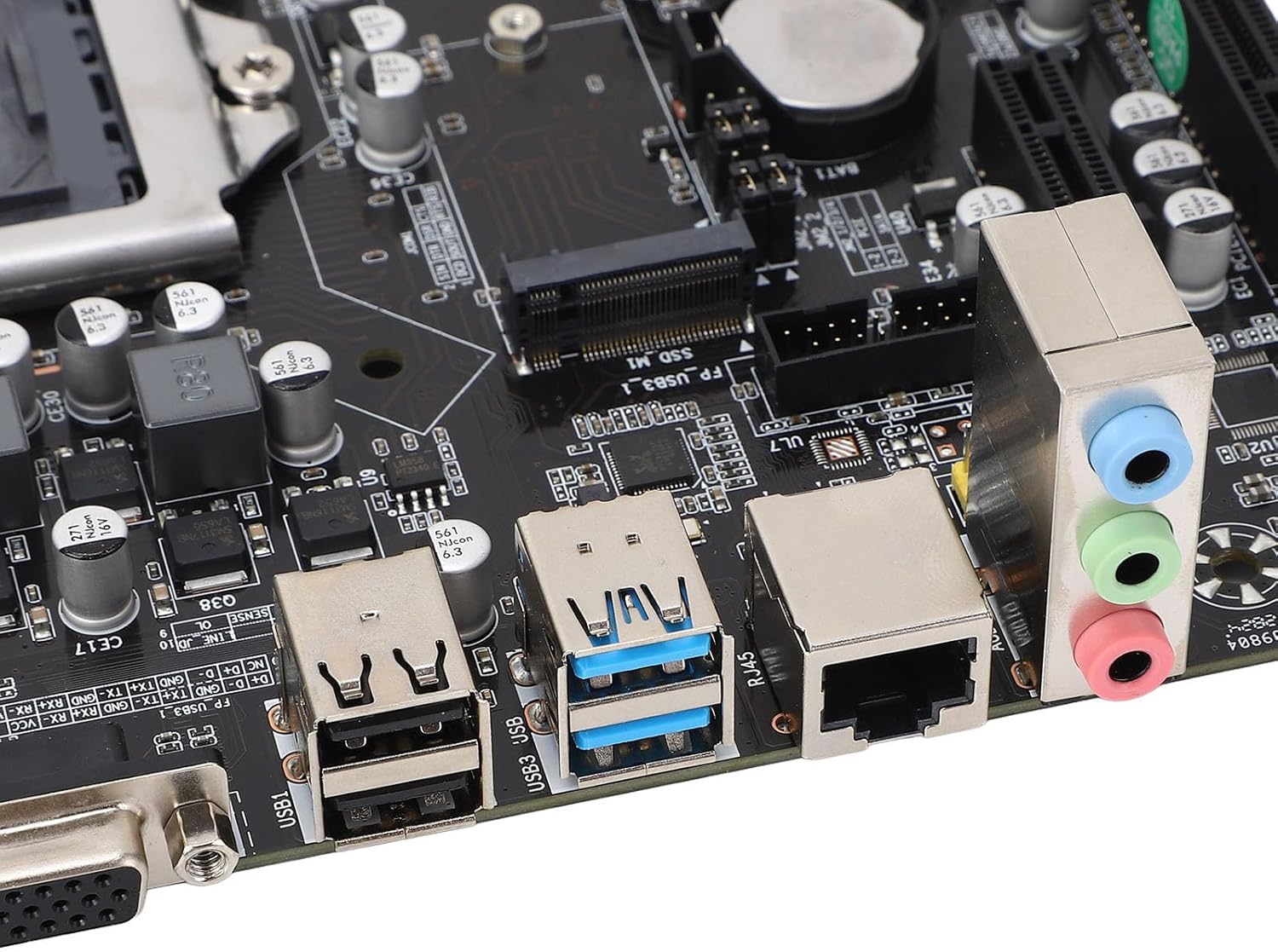
Image: A close-up of the motherboard's rear input/output panel, featuring USB 3.0, USB 2.0, VGA, HDMI, Ethernet, and audio ports.
Operating Instructions
- After all components are installed and connected, close your computer case.
- Connect the power cord to your power supply and turn on the power switch.
- Press the power button on your computer case.
- During startup, you can press the designated key (usually DEL or F2) to enter the BIOS/UEFI setup utility to configure system settings, boot order, and other advanced options.
- Install your preferred operating system (e.g., Windows, Linux) from a bootable USB drive or DVD.
Maintenance
- Dust Removal: Regularly clean dust from inside your computer case and motherboard components using compressed air. Ensure the system is powered off and unplugged before cleaning.
- BIOS Updates: Check the manufacturer's website for BIOS updates. Only update the BIOS if necessary and follow the instructions carefully to avoid system instability.
- Component Checks: Periodically check all cable connections (power, data) to ensure they are secure.
Troubleshooting
- No Power: Ensure all power cables (24-pin ATX, 4-pin CPU) are securely connected. Check your power supply unit (PSU) and wall outlet.
- No Display: Verify that your monitor is connected to the correct video output (VGA or HDMI) on the motherboard or dedicated graphics card. Reseat the graphics card and RAM modules.
- System Instability/Crashes: This can be caused by incompatible RAM, overheating, or faulty components. Check RAM compatibility and ensure CPU cooler is properly installed.
- Boot Device Not Found: Check SATA/NVME cable connections. Verify boot order in BIOS/UEFI settings.
- Form Factor Note: While listed as ITX, some users have reported challenges with dual-slot video cards in certain mini-ITX cases. Always verify case compatibility with your chosen components before final assembly.
Warranty and Support
For warranty information and technical support, please refer to the documentation provided with your purchase or visit the official Diyeeni website. Keep your proof of purchase for warranty claims.
You can visit the Diyeeni store for more products and support: Diyeeni Store