1. Introduction
The MiOYOOW GY21145-2 is a multifunctional voltmeter and ammeter DIY kit designed for laboratory and testing environments. This kit integrates various functions, including voltage and current measurement, temperature sensing, logic level detection, circuit continuity testing, and signal frequency/duty cycle analysis. It also features a PWM adjustable signal generator and provides dual power outputs (3.3V and 5V) for diverse applications. The dual LED screens enhance measurement convenience. This kit offers a practical learning experience, combining theoretical knowledge with hands-on soldering practice.
Key Features:
- All-in-one Experiment DIY Kit: Measures voltage, current, temperature, logic level, circuit on-off, signal frequency, and duty cycle. Functions as a PWM adjustable signal generator with 3.3V and 5V power outputs.
- PWM Adjustable Function Generator: Frequency range: 1Hz-31.2KHz; Duty cycle: 0-100%. Suitable for motor drivers, steering gear, LED drivers, microcontrollers, and various measuring instruments.
- Voltage and Current Tester: Voltage measurement range: 0-30V; Current measurement range: 0-2A. Provides accurate real-time circuit monitoring.
- Soldering Learning Project: Designed for practical learning and improving soldering skills. Requires basic electronic theoretical knowledge and hands-on ability.
2. Components Overview
The MiOYOOW GY21145-2 kit includes all necessary components for assembly. Familiarize yourself with the parts before beginning the soldering process.

Figure 2.1: All components included in the MiOYOOW Electronics DIY Kit, laid out on a table, including the main PCB, acrylic casing parts, resistors, capacitors, LEDs, switches, and connection wires.
The main circuit board features clearly labeled connection points and components. Understanding the layout is crucial for correct assembly and operation.

Figure 2.2: Detailed diagram of the MiOYOOW Electronics DIY Kit circuit board, highlighting key areas such as the display screen, NTC temperature sensor, input/output terminals for voltage, current, and PWM signals, and adjustment potentiometers.
3. Assembly Instructions
This product is a DIY kit requiring assembly and soldering. A detailed paper instruction manual with pictures is included in the package. For a digital version, scan the QR code provided in the paper manual or download the PDF document from the product page on Amazon under 'Product Guides and Documents'. Ensure you have basic electronic theoretical knowledge and soldering skills before attempting assembly.

Figure 3.1: A user engaged in soldering, demonstrating the hands-on nature of assembling the MiOYOOW Electronics DIY Kit.
4. Operating Instructions
The assembled MiOYOOW GY21145-2 unit offers multiple testing and generation functions. Use the SW2 button to cycle through different measurement modes.
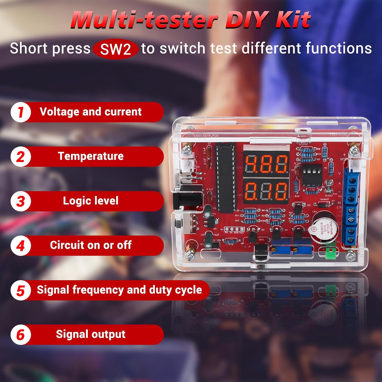
Figure 4.1: The assembled MiOYOOW Multi-tester DIY Kit, illustrating its six primary functions accessible via the SW2 button.
4.1. Voltage and Current Measurement
To measure voltage and current, connect the power supply and the circuit under test to the appropriate terminals. The upper display shows voltage, and the lower display shows current. For the first current measurement, calibration is required: long-press the button until the digital tube flashes.
Video 4.1.1: This video demonstrates how to measure voltage and current using the MiOYOOW GY21145-2 kit. It shows connecting the device to a power supply and a motor, then reading the voltage and current values on the dual LED displays.
4.2. Temperature Measurement
Switch to temperature measurement mode by short-pressing SW2. The upper display shows the current ambient temperature, while the lower display shows the external measured temperature using the NTC sensor. Connect the NTC sensor to the designated terminals and immerse it in the substance to be measured, for example, water.
Video 4.2.1: This video illustrates the process of measuring temperature with the MiOYOOW GY21145-2 kit. It shows how to switch to temperature mode and use the external NTC sensor to measure the temperature of water.
4.3. Logic Level Measurement
To measure logic levels, short-press SW2 to enter the logic level measurement function. Connect the measurement interface to the circuit point you wish to test. The display will indicate whether the interface is at a low or high logic level. If the display shows "---", it indicates that no voltage is measured or the circuit is not powered.
Video 4.3.1: This video demonstrates how to measure logic levels using the MiOYOOW GY21145-2 kit. It shows connecting the measurement probes to a circuit board to determine if a point is at a high or low logic level.
4.4. Circuit On/Off Measurement (Continuity)
To test circuit continuity, short-press SW2 to switch to the circuit on/off measurement mode. Connect the measurement probes to the points you want to test. A buzzer sound indicates a short circuit (continuity), while no sound indicates an open circuit (no continuity).
Video 4.4.1: This video demonstrates the circuit on/off measurement function of the MiOYOOW GY21145-2 kit. It shows how to test for continuity on a circuit board, with a buzzer indicating a short circuit.
4.5. PWM Pulse Output
The kit can generate PWM pulses. Short-press SW2 to switch to the pulse output function. The upper display shows the frequency, and the lower display shows the duty cycle. You can adjust the duty cycle and frequency using the potentiometers to control devices like motors. The pulse output amplitude can be selected between 3.3V and 5V using a short circuit cap.
Video 4.5.1: This video demonstrates the PWM pulse output function of the MiOYOOW GY21145-2 kit. It shows how to adjust the duty cycle and frequency to control a motor's speed and how to select the output amplitude.
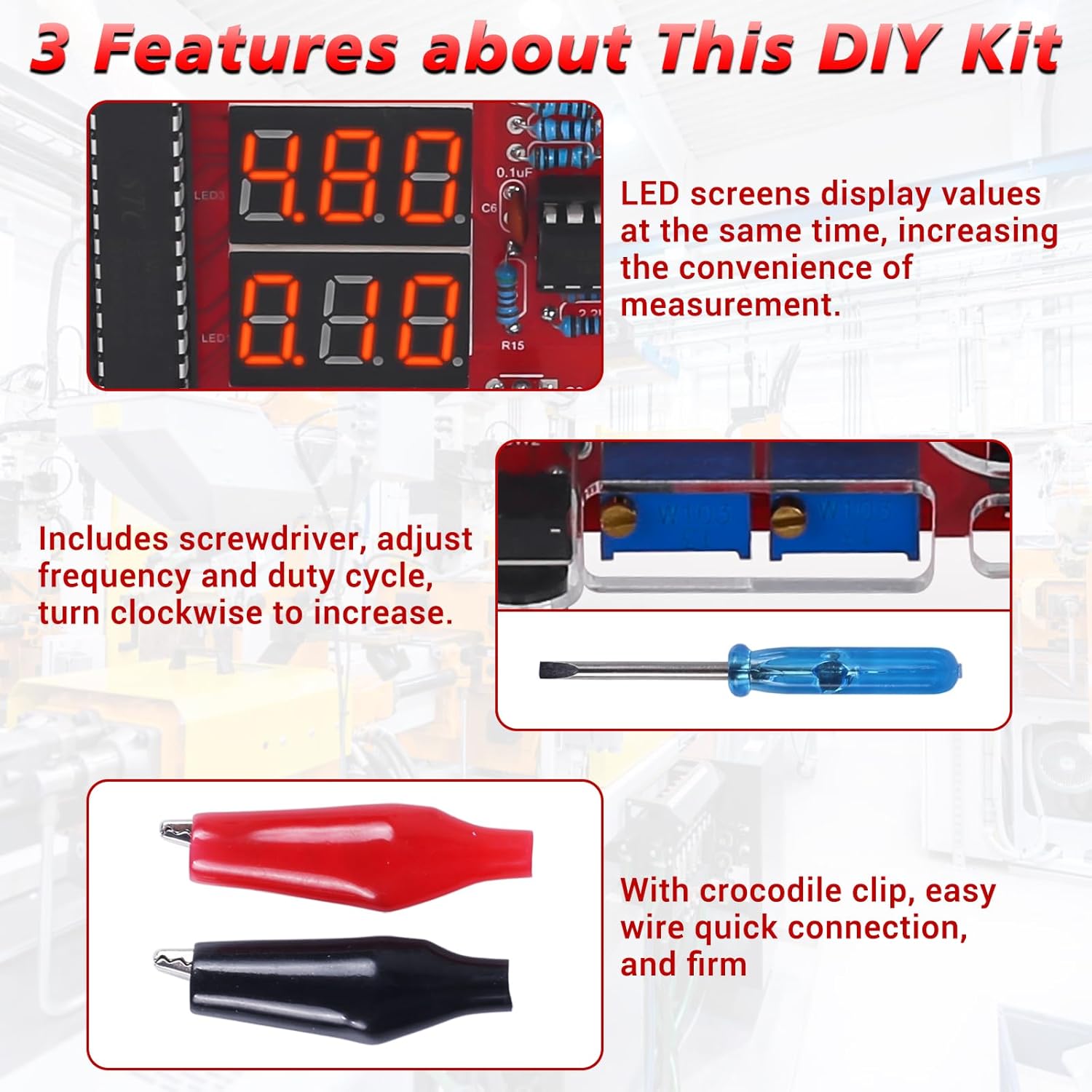
Figure 4.5.2: Close-up views of the dual LED screens displaying values, the adjustment screwdriver used for frequency and duty cycle, and the included crocodile clips for easy and secure connections.
5. Specifications
| Feature | Specification |
|---|---|
| Manufacturer | MiOYOOW |
| Item Weight | 140 g |
| Product Dimensions | 12.5 x 8.5 x 1.9 cm |
| Item Model Number | GY21145-2 |
| Color | Transparent |
| Power Source Type | DC |
| Included Components | Circuit board (and other DIY kit components) |
| Measurement Type | Voltmeter, Ammeter, Temperature, Logic Level, Frequency, Duty Cycle |
| Maximum Operating Voltage | 30 Volts |
| Voltage Measurement Range | 0-30V |
| Current Measurement Range | 0-2A |
| PWM Frequency Range | 1Hz-31.2KHz |
| PWM Duty Cycle | 0-100% |

Figure 5.1: Product dimensions of the assembled MiOYOOW GY21145-2 unit.
6. Maintenance and Care
To ensure the longevity and optimal performance of your MiOYOOW GY21145-2 kit, follow these maintenance guidelines:
- Keep the device clean and free from dust and debris. Use a soft, dry cloth for cleaning.
- Avoid exposing the device to extreme temperatures, humidity, or direct sunlight.
- Store the kit in a safe place when not in use to prevent physical damage.
- Regularly check all connections for tightness and ensure no wires are frayed or damaged.
- If any components appear damaged or worn, replace them with appropriate substitutes.
7. Troubleshooting
If you encounter issues with your MiOYOOW GY21145-2 kit, consider the following common troubleshooting steps:
- No Power: Ensure the USB power supply is correctly connected and functioning. Check all power connections on the circuit board.
- Incorrect Readings: Verify that all components are correctly soldered and that the measurement probes are securely connected to the correct terminals. For current measurement, ensure initial calibration has been performed.
- Display Issues: Check for loose connections to the LED displays. If the display shows "---" during logic level measurement, ensure the circuit under test is powered.
- PWM Output Not Working: Confirm that the device is in PWM pulse output mode. Check the frequency and duty cycle settings. Ensure the short circuit cap for amplitude selection is correctly placed.
- Buzzer Not Sounding (Continuity Test): Ensure the device is in circuit on/off measurement mode. Verify that the probes are making good contact with the test points.
For more detailed troubleshooting or persistent issues, refer to the comprehensive PDF manual available on the product's Amazon page or contact MiOYOOW customer support.
8. Warranty and Support
MiOYOOW products are designed for quality and performance. For specific warranty information, please refer to the documentation included with your purchase or visit the official MiOYOOW store on Amazon. For technical support, inquiries, or assistance with your DIY kit, please contact MiOYOOW customer service through the Amazon platform or their official website. Please have your model number (GY21145-2) and purchase details ready when contacting support.