1. Introduction
This manual provides comprehensive instructions for the installation, operation, maintenance, and troubleshooting of your Linksys LGS352MPC 48 Port Gigabit Network PoE+ Switch. Please read this manual thoroughly before using the device to ensure proper setup and functionality.
Product Overview
The Linksys LGS352MPC is a 48-port managed Gigabit PoE+ switch designed to expand network capacity and provide high-speed data transfers. It features 48 Gigabit Ethernet ports, 4 x 10G SFP+ uplink slots, and a 740W power budget for Power over Ethernet Plus (PoE+) devices. Advanced capabilities include Quality of Service (QoS) traffic prioritization, VLAN support, static routing, and IGMP for optimized network performance and enhanced security.

Image: Overview of the Linksys LGS352MPC switch, highlighting its 48x 1Gb Ethernet ports, 4x 10Gb SFP+ Uplink ports, 176 Gbps switching capacity, QoS traffic prioritization, and 740W power budget for PoE+.
2. Package Contents
Verify that your package contains the following items:
- 1x Linksys LGS352MPC 48-Port Managed Gigabit PoE+ Switch
- 1x Power Adapter
- 1x Quick Start Guide
- 1x Rack Mount Kit

Image: Contents of the Linksys LGS352MPC package, including the switch, power adapter, quick start guide, and rack mount kit.
3. Setup
3.1 Physical Installation
The Linksys LGS352MPC switch can be installed on a desktop, mounted on a wall, or installed in a standard 19-inch rack.
Desktop Placement:
- Place the switch on a flat, stable surface.
- Ensure adequate ventilation around the device.
Rack Mounting:
- Attach the included rack-mount brackets to the sides of the switch using the provided screws.
- Secure the switch into a standard 19-inch equipment rack.

Image: Front view of the Linksys LGS352MPC switch, showing the 48 Ethernet ports and 4 SFP+ uplink ports.
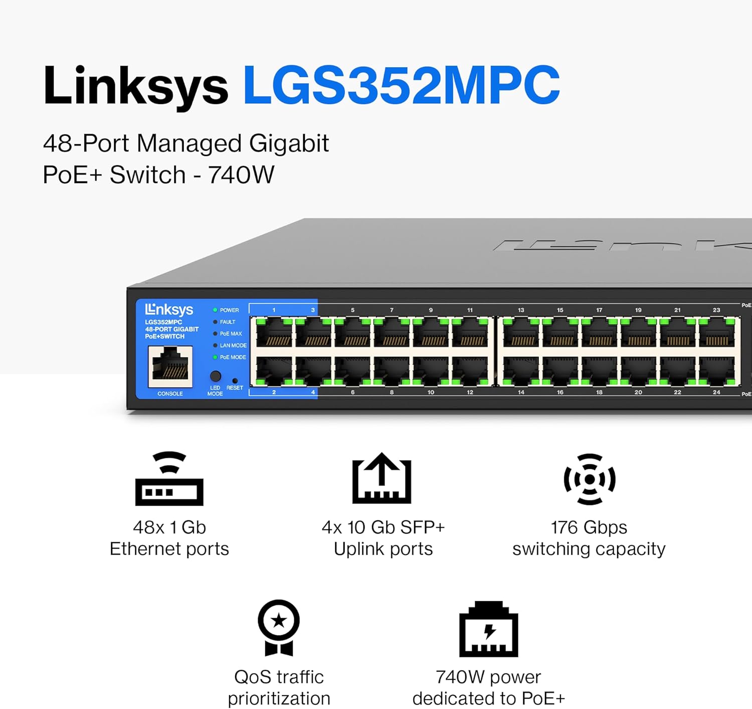
Image: Detailed view of the front panel, including LED indicators for Power, Fault, PoE Max, LAN Mode, and PoE Mode, along with the console port.
3.2 Power Connection
- Connect the power adapter to the power input on the rear of the switch.
- Plug the other end of the power adapter into a suitable electrical outlet.
- Verify the Power LED on the front panel illuminates, indicating the switch is receiving power.

Image: Rear panel of the switch, displaying the AC power input connector.
3.3 Network Connections
- Connect Ethernet cables from your network devices (computers, IP cameras, access points, etc.) to the RJ45 ports (1-48) on the front of the switch.
- For high-speed uplinks to your core network or other switches, insert SFP+ transceivers into the 10G SFP+ slots (49-52) and connect appropriate fiber optic cables.
- The switch supports Power over Ethernet (PoE) and PoE+ on its RJ45 ports, automatically providing power to compatible devices.

Image: Step-by-step diagram showing how to plug in the switch and connect various devices like computers, printers, and gaming consoles.
4. Operating the Switch
4.1 Basic Operation
Once powered on and devices are connected, the switch automatically facilitates network communication. The Gigabit ports provide high-speed data transfer, minimizing interference for streaming and large file transfers.

Image: The switch illustrating Gigabit performance, minimizing transfer times and enabling high-bandwidth file streaming to connected devices like computers, smart TVs, printers, and gaming consoles.
4.2 LED Indicators
The front panel LEDs provide status information:
- POWER: Solid green indicates the switch is powered on.
- FAULT: Indicates a system fault. Refer to troubleshooting if illuminated.
- PoE MAX: Indicates the Power over Ethernet budget is nearing its maximum capacity.
- LAN MODE: Indicates the operational mode of the LAN ports.
- PoE MODE: Indicates the Power over Ethernet status of individual ports.
4.3 Management Interface
The LGS352MPC is a managed switch, offering a web-based management interface for advanced configuration. Access the interface by entering the switch's IP address into a web browser. Refer to the Quick Start Guide for initial IP address and login credentials.
Through the management interface, you can configure:
- Quality of Service (QoS): Prioritize network traffic for critical applications.
- VLANs: Create virtual local area networks for network segmentation and security.
- Static Routing: Configure static routes for specific network paths.
- MAC-based Port Security: Restrict network access to specific MAC addresses on individual ports.
- IGMP Snooping: Optimize multicast traffic.

Image: The switch with an overlay explaining QoS traffic prioritization, ensuring mission-critical data throughput is maintained regardless of network congestion. Auto-sensing ports optimize speed for each connected device.

Image: The switch with an overlay explaining PoE+ capabilities, which provides power and flexibility, saving on costs and simplifying installations for IP cameras and wireless access points.

Image: A network diagram illustrating how the managed Gigabit switch provides secure, speedy network expansion and prioritizes traffic with QoS for optimum performance, connecting various PoE and non-PoE devices.
5. Maintenance
5.1 Firmware Updates
Regularly check the Linksys support website for firmware updates. Firmware updates can provide new features, performance improvements, and security enhancements. Follow the instructions provided with the firmware update package for proper installation.
5.2 Cleaning
To clean the switch, power it off and disconnect it from the power source. Use a soft, dry cloth to wipe the exterior. Do not use liquid or aerosol cleaners.
5.3 Environmental Considerations
Ensure the switch is operated within its specified temperature and humidity ranges. Maintain adequate airflow around the device to prevent overheating, especially in rack-mounted installations.
6. Troubleshooting
6.1 No Power
- Verify the power cord is securely connected to both the switch and the electrical outlet.
- Ensure the electrical outlet is functional by testing it with another device.
6.2 No Network Connectivity
- Check that Ethernet cables are securely connected to both the switch and the network devices.
- Verify the link/activity LEDs on the switch ports are illuminated for connected devices.
- Ensure network device drivers are up to date.
- If using PoE, check the PoE MODE LED for the specific port to ensure power is being delivered.
6.3 Slow Network Performance
- Confirm all connected devices and cables support Gigabit Ethernet speeds.
- Check for excessive network traffic or bottlenecks on other network segments.
- Review QoS settings in the management interface to ensure critical traffic is prioritized correctly.
6.4 Excessive Noise
The switch contains cooling fans. While some fan noise is normal, excessively loud operation (e.g., 60-70 dBa as noted in some user experiences) may indicate high internal temperatures or fan issues. Ensure adequate ventilation and ambient temperature. If the noise persists and is disruptive, contact Linksys support.
7. Specifications
| Feature | Detail |
|---|---|
| Model Number | LGS352MPC |
| Number of Ports | 48 x Gigabit Ethernet, 4 x 10G SFP+ Uplink |
| PoE+ Budget | 740 Watts |
| Switching Capacity | 176 Gbps |
| Data Transfer Rate | 1000 Mbps (Gigabit) |
| Interface Type | PoE, SFP |
| Case Material | Metal |
| Dimensions (LxWxH) | 12.09 x 17.24 x 1.77 inches |
| Weight | 12.67 pounds (5.76 Kilograms) |
| Voltage | 48 Volts (DC) |
| UPC | 745883865116 |
8. Warranty and Support
8.1 Warranty Information
The Linksys LGS352MPC switch is backed by a 5 1/2 Year warranty. Please retain your proof of purchase for warranty claims.
8.2 Technical Support
For technical assistance, please contact Linksys customer support. Free 24/7 technical support is available.
Visit the official Linksys website for support resources, FAQs, and contact information: Linksys Support