
Yoidesu X99 F2
Yoidesu X99 F2 E-ATX Motherboard User Manual
Model: X99 F2 (Yoidesu6cp28vge4b)
Introduction
Welcome to the user manual for the Yoidesu X99 F2 E-ATX Motherboard. This document provides essential information for the proper installation, operation, and maintenance of your motherboard. Please read this manual thoroughly before proceeding with installation to ensure optimal performance and longevity of your system.
Technical Specifications
| Feature | Specification |
|---|---|
| Item Type | DDR4 Motherboard |
| Material | PCB |
| Built-in Battery | CR2032x1 240mAh |
| Motherboard Model | X99 F2 |
| Motherboard Type | E ATX |
| CPU Socket Type | LGA2011 V3 V4 |
| Compatible Processors | Intel Core i3/i5/i7/i9 (LGA2011 V3 V4), Intel Xeon E5 v3, v4, v5 |
| Chipset Type | Intel X99 |
| Memory Slots | 8 x DDR4 |
| Max Memory Capacity | 256GB |
| Graphics Card Slot | 2 x PCIe 16X |
| NIC | 2 x Gigabit Adaptive NIC |
| HDD Interface | 10 x SATA3.0, 1 x M.2 NVME Interface |
| Display Interface | PS/2 Keyboard and Mouse |
| Power Connector | 2 x 8-pin, 1 x 24-pin |
| USB Interface | USB3.0 x 6, USB2.0 x 6 (Front USB3.0 x 2, USB2.0 x 2) |
| Expansion Interface | 3 x PCIe 1X, 1 x COM Pins |
| Item Weight | 3.73 pounds |
| Package Dimensions | 14.17 x 13.78 x 3.15 inches |
| Platform | Windows XP (Minimum OS compatibility) |
Setup and Installation
This section guides you through the physical installation of the Yoidesu X99 F2 E-ATX Motherboard into your computer chassis and connecting essential components.
1. Preparation
- Ensure your power supply is disconnected from the wall outlet.
- Work on a clean, static-free surface. Use an anti-static wrist strap if available.
- Gather necessary tools: screwdriver, thermal paste (for CPU), and cable ties.
2. Installing the CPU
Locate the LGA2011 V3 V4 CPU sockets on the motherboard.
- Open the CPU socket retention mechanism.
- Carefully align the CPU with the socket, ensuring the triangular markers match. Do not force the CPU into the socket.
- Close the retention mechanism to secure the CPU.
- Apply a thin, even layer of thermal paste to the top of the CPU.

Image: Overview of the Yoidesu X99 F2 E-ATX Motherboard, showing the dual CPU sockets and memory slots.
3. Installing Memory (RAM)
The motherboard supports 8xDDR4 memory modules.
- Open the clips at both ends of the DDR4 memory slots.
- Align the memory module with the slot, ensuring the notch on the module matches the key in the slot.
- Press down firmly on both ends of the memory module until the clips snap into place.

Image: The X99 F2 motherboard with its 8 DDR4 memory slots and dual CPU sockets clearly visible.
4. Installing Storage Devices (M.2 NVME / SATA)
The motherboard features one M.2 NVME interface and ten SATA3.0 interfaces.
- M.2 NVME SSD: Locate the M.2 slot. Insert the M.2 SSD at an angle and then gently push it down, securing it with the provided screw.
- SATA Drives: Connect your SATA SSDs or HDDs to the SATA3.0 ports using SATA data cables. Connect the power cables from your power supply to the drives.
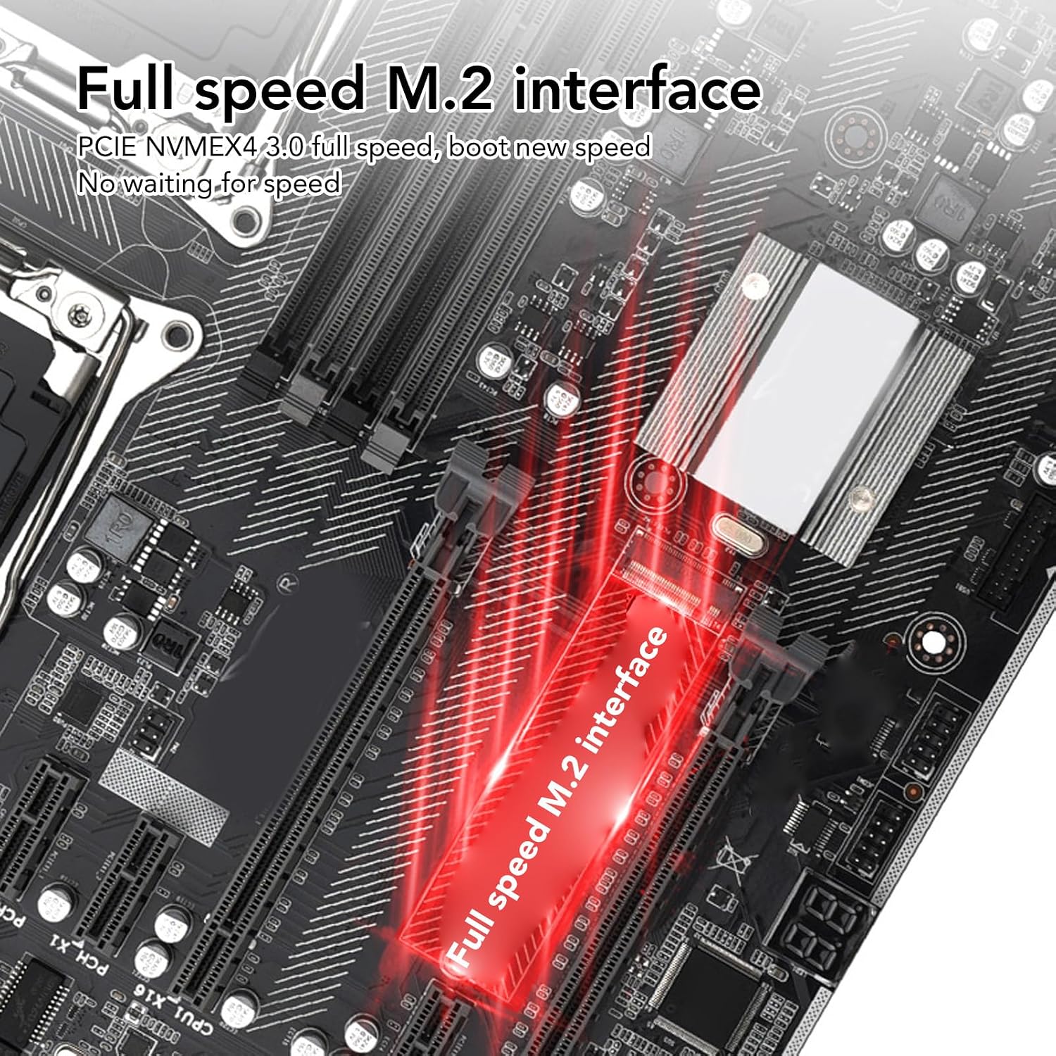
Image: The full-speed M.2 NVME interface on the motherboard.
5. Installing Graphics Cards (PCIe)
The motherboard supports two PCIe 16X graphics cards.
- Open the retention clip at the end of the PCIe 16X slot.
- Align your graphics card with the slot and press down firmly until it is fully seated and the retention clip snaps into place.
- Secure the graphics card to your chassis with screws.
- Connect any necessary PCIe power cables from your power supply to the graphics card(s).

Image: The PCIe 16X slots, illustrating support for dual graphics card configurations.
6. Connecting Power Supply
Connect the 24-pin ATX power connector and the two 8-pin CPU power connectors from your power supply to the corresponding ports on the motherboard.
7. Connecting Front Panel Headers
Refer to the motherboard diagram to connect the front panel headers (power button, reset button, HDD LED, power LED, front USB, front audio) to their respective pins.

Image: Motherboard structure diagram with labeled components and connectors.
Operating Instructions
Initial Boot-up
- After all components are installed and connected, connect your monitor, keyboard, and mouse.
- Connect the power supply to a wall outlet and turn on the power.
- Press the power button on your computer case.
- The system should boot to the BIOS/UEFI interface or begin the operating system installation process.
BIOS/UEFI Configuration
To enter the BIOS/UEFI setup, typically press the DEL or F2 key during the initial boot sequence. Here you can configure boot order, system time, and other advanced settings.
Digital Diagnostic Function
The motherboard includes a digital diagnostic function (POST code display) that shows a two-digit code during boot-up. This code can help identify hardware issues if the system fails to boot. Refer to the motherboard's specific POST code list for detailed explanations.
Maintenance
- Dust Removal: Regularly clean dust from the motherboard and components using compressed air. Ensure the system is powered off and unplugged before cleaning.
- Firmware Updates: Periodically check the manufacturer's website for BIOS/UEFI updates. Follow the update instructions carefully to avoid system instability.
- Cable Management: Ensure cables are neatly routed to improve airflow and prevent interference.
- Environmental Conditions: Operate the motherboard in a well-ventilated area with stable temperature and humidity to prevent overheating and component degradation.
Troubleshooting
No Power / No Boot
- Check all power connections (24-pin ATX, 8-pin CPU, GPU power).
- Ensure the power supply is switched on and connected to a working outlet.
- Verify front panel power button connection.
- Try booting with minimal components (CPU, one RAM stick, GPU if no integrated graphics).
No Display
- Ensure the monitor is connected to the graphics card (not the motherboard, unless integrated graphics are used).
- Check graphics card power connections.
- Reseat the graphics card and memory modules.
- Test with a different monitor or display cable.
System Instability / Crashes
- Check CPU and GPU temperatures. Ensure cooling solutions are properly installed.
- Run memory diagnostic tools to check for faulty RAM.
- Update BIOS/UEFI and drivers to the latest versions.
- Verify power supply wattage is sufficient for all components.
POST Code Errors
If the digital diagnostic display shows an error code, consult the motherboard's specific POST code manual (often available on the manufacturer's support website) to identify the issue.
Warranty and Support
For warranty information and technical support, please refer to the documentation provided with your purchase or visit the official Yoidesu website. Keep your proof of purchase for warranty claims.
Visit the Yoidesu Store on Amazon for more products and support.
Package Contents
The following items are included with your Yoidesu X99 F2 E-ATX Motherboard:
- 1 x Mainboard (with Inbuilt Battery)
- 1 x Metal Plate
- 1 x Connection Cable
- 2 x Bracket
- 20 x Screw
Ask a question about this manual
Ask about setup, troubleshooting, compatibility, parts, safety, or missing instructions. Manuals+ will review the question and use this page’s manual context to help answer it.