
1. Product Overview
The YWBL-WH Motor Frequency Converter is a digital display Variable Frequency Drive (VFD) designed for controlling AC motors. It features a user-friendly keypad and digital display for easy operation, making it suitable for various applications such as fans, pumps, and power tools.

Figure 1: Front angled view of the YWBL-WH Motor Frequency Converter.
Key Features:
- Durable ABS Shell: Constructed from industrial-grade ABS plastic, offering high resistance to impact and heat, strong flame retardancy, and overall robust performance.
- User-Friendly Interface: Equipped with an intuitive keypad and a clear digital display for straightforward operation and monitoring.
- Efficient Heat Dissipation: Features an integrated, oversized heat sink and a low-noise fan, providing superior cooling performance compared to similar products.
- High-Performance Motherboard: Utilizes a premium, intelligent, and efficient motherboard with advanced protection features and comprehensive functionalities.
- Enhanced Stability: Full SMD (Surface-Mount Device) design for all internal components significantly boosts the machine's performance stability.
2. Safety Instructions and Precautions
Failure to follow these safety instructions may result in serious injury or equipment damage. Always prioritize safety during installation, operation, and maintenance.
- Before proceeding with any wiring, ensure that the input power supply to the device is completely disconnected.
- All wiring operations must be performed by qualified professional electrical engineers.
- The grounding terminal must be properly grounded to prevent electrical shock.
- After completing the wiring for the emergency stop circuit, always verify that its action is valid and functional.
- Do not connect the inverter's output cable to the equipment casing, and do not short-circuit the output cable.
- Verify that the AC main circuit supply voltage is consistent with the rated voltage of the inverter (380-440V AC).
- Do not perform withstand voltage tests on the inverter.
- Connect the braking resistor strictly according to the provided wiring diagram.
- Do not connect the power cable to the U, V, W output terminals. These are for motor connection only.
- Do not connect a contactor to the output circuit of the inverter.
- Ensure the protective cover is securely installed before powering on the device. When removing the cover, always disconnect the power supply first.
- If the inverter has a reset and retry function, ensure it is not located near mechanical equipment, as it may suddenly reset after an alarm stops, potentially causing unexpected movement.
- After confirming that the operation signal has been cut, the alarm can be reset. If the alarm is reset while the operation signal is still active, the inverter may start suddenly.
- Do not touch the inverter terminals. High voltage is present, which is extremely dangerous.
- Never change wiring, remove, or install components while the power supply is connected.
3. Installation and Wiring
Proper installation and wiring are crucial for the safe and efficient operation of the frequency converter. Refer to the diagrams and instructions below carefully.
3.1 Terminal Overview
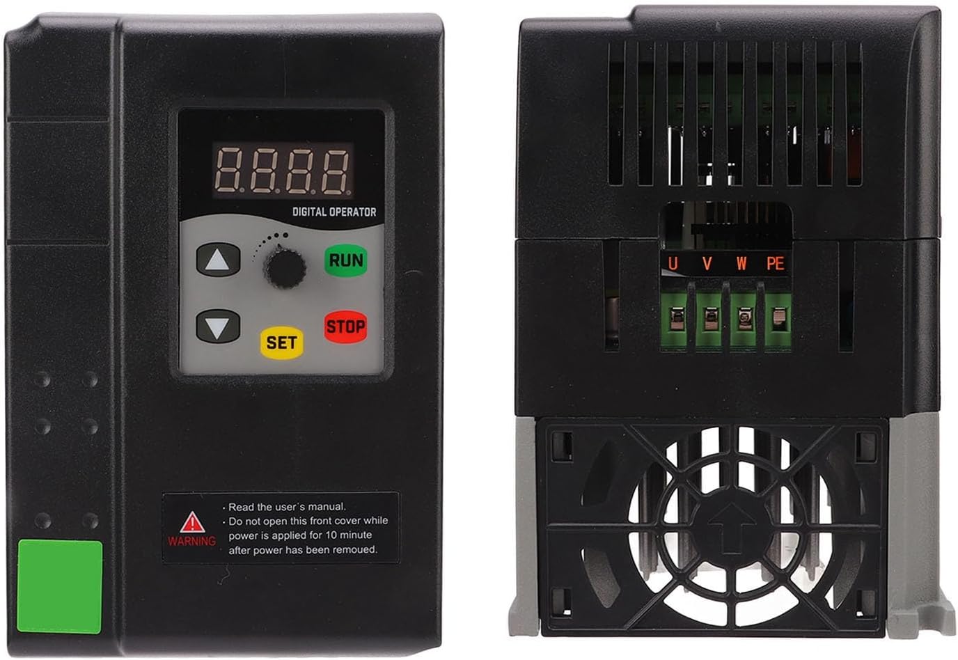
Figure 2: Rear view showing the main power and motor terminals (U, V, W, PE).
3.2 Wiring Diagram
The following diagrams illustrate the connections for power input, motor output, and control signals. Ensure all connections are secure and comply with local electrical codes.

Figure 3: Detailed wiring diagram including input, output, control signals, and braking resistor connections.

Figure 4: Simplified wiring diagram with terminal definitions for control and power connections.
Terminal Definitions:
| Terminal | Description |
|---|---|
| COM | Signal Common |
| S1-S5 | Digital Input (Function Terminal) |
| GND | Signal Common |
| AVI | Analog Voltage Input |
| +10V | Frequency Setting Potentiometer Power Supply |
| ACI | Analog Current Input |
| AO | Analog Output Signal |
| RA, RB, RC | Relay Output (Factory set as Fault Indication) |
| R, S, T | Three-Phase AC Power Input (380-440V) |
| U, V, W | Three-Phase Motor Output |
| PE | Protective Earth Ground |
| P, B | Braking Resistor Connection |
4. Operation
The YWBL-WH VFD features a digital operator panel for easy control and monitoring of motor speed and parameters.
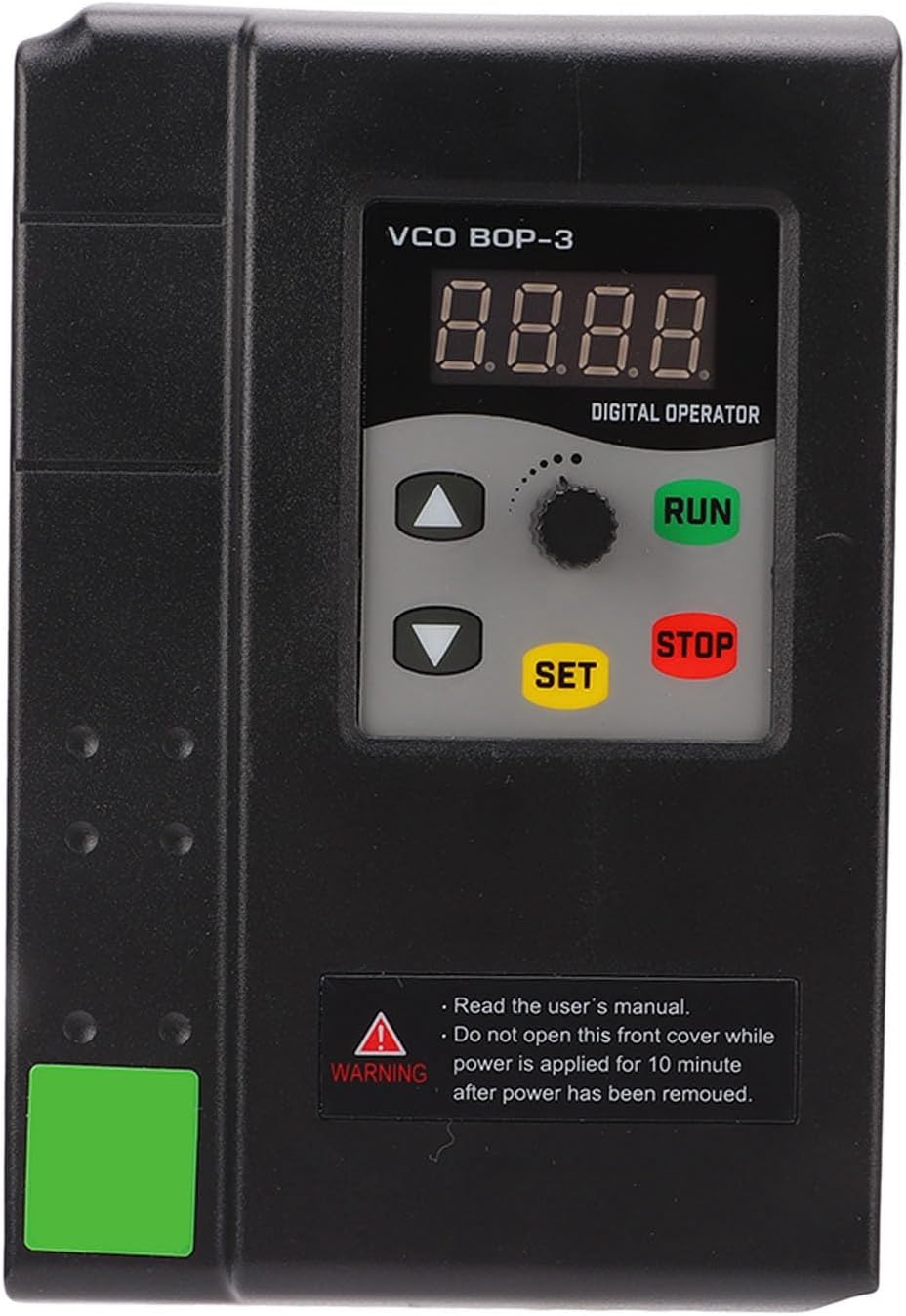
Figure 5: Digital operator panel with display and control buttons.
4.1 Keypad Functions
- Digital Display: Shows current frequency, output voltage, current, and various parameter settings.
- RUN Button: Initiates motor operation.
- STOP Button: Halts motor operation.
- SET Button: Enters parameter setting mode or confirms selections.
- Up/Down Arrows: Navigate through menus or adjust parameter values.
- Rotary Knob: Used for fine-tuning frequency or parameter values.
For detailed parameter settings and advanced functions, please refer to the comprehensive user manual provided with the product. Ensure all safety precautions are observed before operating the device.
5. Maintenance
Regular maintenance ensures the longevity and optimal performance of your YWBL-WH Motor Frequency Converter.
5.1 Heat Dissipation
The VFD is designed with a large integrated heat sink and a small, low-noise fan to ensure efficient heat dissipation. To maintain optimal cooling:
- Ensure adequate ventilation around the unit. Do not block air vents.
- Regularly inspect and clean the fan and heat sink to prevent dust accumulation, which can impede airflow and lead to overheating.
- Operate the device within its specified ambient temperature range (-25°C to +55°C).

Figure 6: Bottom view highlighting the cooling fan for heat dissipation.
5.2 General Care
- Keep the unit clean and free from dust, moisture, and corrosive substances.
- Periodically check all wiring connections for tightness and signs of wear or damage.
- Avoid exposing the device to direct sunlight or extreme environmental conditions.
6. Troubleshooting
This section provides general guidance for common issues. For specific error codes or complex problems, consult the full product manual or contact technical support.
Common Issues and Solutions:
- No Power/Display Off:
- Check input power supply connections (R, S, T).
- Ensure the main circuit AC supply voltage matches the inverter's rated voltage (380-440V).
- Verify that the protective cover is correctly installed.
- Motor Not Running:
- Confirm the RUN button has been pressed.
- Check motor wiring (U, V, W) for correct connection and continuity.
- Ensure no emergency stop circuit is active.
- Check for any error codes on the digital display and consult the manual for their meaning.
- Overheating/Fan Noise:
- Inspect fan and heat sink for dust or obstructions. Clean if necessary.
- Ensure adequate clearance for airflow around the unit.
- Verify ambient temperature is within the specified operating range.
- Unexpected Motor Start/Reset:
- If the inverter has a reset/retry function, ensure it is not near mechanical equipment.
- Ensure the operation signal is completely cut before resetting any alarms.
7. Specifications
| Feature | Specification |
|---|---|
| Brand | YWBL-WH |
| Model Number | YWBL-WHc3n4vdh1p8-11 |
| ASIN | B0CCVVWPM3 |
| Manufacturer | YWBL-WH |
| Country of Origin | China |
| Input Voltage | Three-phase 380-440V AC |
| Output Voltage | Three-phase 0-440V AC |
| Rated Power | 0.75 kW |
| Storage Temperature | -25°C to +55°C |
| Material | Industrial-grade ABS Plastic |
8. Warranty and Support
For warranty information, technical support, or service inquiries, please refer to the documentation included with your purchase or contact your vendor. Keep your purchase receipt as proof of purchase for any warranty claims.