1. Product Overview
The NCLTHS 1200LBS Electric Magnetic Lock is a robust access control solution designed for various door types. It operates in NC (Normally Closed) mode, meaning it is locked when power is supplied and unlocks upon power loss (fail-safe mode). This design ensures security during power outages by allowing egress. The lock provides a strong holding force of 500KG (1200LBS) and is constructed from durable stainless steel with anti-residual magnetism features.
This package includes the electromagnetic lock unit, an armature plate, and Z and L brackets for versatile installation options.

Image 1.1: Overview of the NCLTHS 1200LBS Electric Magnetic Lock with included Z and L brackets and mounting hardware.
2. Package Contents
Please verify that all components are present and undamaged before proceeding with installation.
- 1 x Electromagnetic Lock Unit
- 1 x Armature Plate
- 1 x Z Bracket Set
- 1 x L Bracket Set
- 1 x Screws Pack (various sizes for mounting)
- 1 x User Manual (English)

Image 2.1: Illustration of the components included in the package, such as the lock, armature plate, and mounting hardware.

Image 2.2: Close-up view of the Z and L brackets, essential for various installation types.
3. Technical Specifications
| Feature | Specification |
|---|---|
| Brand | NCLTHS |
| Model | 1200Lbs with Z and L Bracket |
| Holding Force | 500KG (1200LBS) |
| Operating Voltage | DC12V |
| Operating Mode | NC Mode (Fail-Safe) |
| Lock Dimensions (L x W x H) | 10.43'' x 2.95'' x 1.54'' (265x75x39mm) |
| Armature Plate Dimensions (L x W x H) | 7.28'' x 2.36'' x 0.51'' (185x60x13mm) |
| Material | Stainless steel, Aluminum |
| Special Feature | Keyless, Built-in voltage spike suppressor |
| Recommended Uses | Wooden Door, Glass Door, Metal Door, Fire Proof Door, Cabinet |

Image 3.1: Detailed dimensional drawing of the electromagnetic lock and armature plate for precise installation planning.
4. Setup & Installation
Before installation, ensure the power supply is disconnected. Professional installation is recommended for optimal performance and safety.
4.1 Installation Steps
- Prepare the Lock: Loosen the screws on the electromagnetic lock unit to separate the main body from its mounting plate.
- Mount the Lock Body: Secure the main electromagnetic lock unit to the door frame using the appropriate L or Z brackets and screws. Ensure it is firmly attached and aligned with the intended position of the armature plate.
- Install the Armature Plate: Attach the armature plate to the door itself. For inward-swinging doors, Z brackets are typically used. For outward-swinging doors, L brackets are common. Ensure the armature plate aligns perfectly with the electromagnetic lock when the door is closed.
- Secure All Components: Tighten all screws to ensure a secure and stable installation.

Image 4.1: Step-by-step visual guide for installing the electromagnetic lock and armature plate on a door.
4.2 Wiring Diagram
Connect the electromagnetic lock to a DC12V power supply and an access control system (e.g., keypad, exit button) according to the following diagram. The lock operates in NC (Normally Closed) mode.
- Connect the +12V terminal of the power supply to the +12V input of the access control keypad.
- Connect the GND terminal of the power supply to the GND input of the access control keypad.
- Connect the NO (Normally Open) terminal of the exit button to the COM (Common) terminal of the access control keypad.
- Connect the COM terminal of the exit button to the NO (Normally Open) terminal of the magnetic lock.
- Connect the -NC terminal of the magnetic lock to the -COM terminal of the access control keypad.
- Connect the +NC terminal of the magnetic lock to the +12V output of the access control keypad.
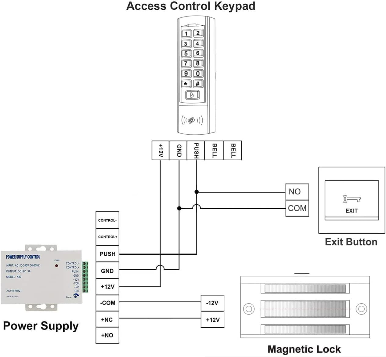
Image 4.2: Detailed wiring schematic showing connections between the magnetic lock, power supply, access control keypad, and exit button.

Image 4.3: View of the internal wiring connections within the electromagnetic lock unit.
5. Operating Instructions
The NCLTHS Electric Magnetic Lock operates as part of an access control system. When power is supplied to the lock, it creates a strong magnetic field that holds the armature plate, keeping the door securely locked. To unlock the door, the power supply to the lock must be interrupted.
5.1 Unlocking the Door
- Via Access Control Keypad: Enter the correct access code on the connected keypad. This will momentarily cut power to the lock, allowing the door to be opened.
- Via Exit Button: Press the exit button located on the secure side of the door. This action will interrupt the power to the lock, releasing the door.
- Power Failure: In the event of a power failure, the lock will automatically disengage (fail-safe mode), allowing the door to be opened.
5.2 Locking the Door
The door will automatically lock when it is closed and power is supplied to the electromagnetic lock. Ensure the door closes completely for proper engagement of the lock and armature plate.
6. Maintenance
Regular maintenance ensures the longevity and reliable operation of your NCLTHS Electric Magnetic Lock.
- Cleaning: Periodically clean the surfaces of the electromagnetic lock and armature plate with a soft, dry cloth. Avoid using abrasive cleaners or solvents that could damage the finish or internal components.
- Inspection: Regularly inspect the lock and armature plate for any signs of wear, corrosion, or damage. Check that all mounting screws are tight.
- Alignment: Ensure the electromagnetic lock and armature plate remain perfectly aligned. Misalignment can reduce holding force and cause premature wear. Adjust if necessary.
- Wiring: Check all wiring connections for looseness or damage. Ensure insulation is intact to prevent short circuits.
7. Troubleshooting
If you encounter issues with your magnetic lock, refer to the following common problems and solutions:
| Problem | Possible Cause | Solution |
|---|---|---|
| Lock does not engage (door does not secure) | No power to the lock; Incorrect wiring; Misalignment of lock and armature plate; Damaged lock unit. | Check power supply and connections; Verify wiring against diagram; Adjust alignment; Contact support if unit is damaged. |
| Lock does not disengage (door remains locked) | Access control system malfunction; Exit button malfunction; Continuous power supply; Lock unit failure. | Check access control system and exit button functionality; Ensure power is correctly interrupted; Contact support. |
| Reduced holding force | Misalignment; Gap between lock and armature plate; Dirty surfaces; Insufficient power. | Adjust alignment; Ensure no debris between surfaces; Clean contact surfaces; Verify power supply voltage. |
| Unusual noise from lock | Loose components; Vibration. | Check and tighten all mounting screws; Ensure stable installation. |
8. Warranty & Support
NCLTHS products are manufactured to high-quality standards. This product comes with a standard manufacturer's warranty against defects in materials and workmanship. Please refer to your purchase documentation for specific warranty terms and duration.
For technical support, troubleshooting assistance, or warranty claims, please contact NCLTHS customer service through the retailer where the product was purchased or visit the official NCLTHS website.
Customer Service Contact: Refer to your purchase invoice or the NCLTHS official website for current contact information.