1. Introduction
This manual provides detailed instructions for the installation, setup, operation, and maintenance of the RATTMMOTOR 3-Axis Nema23 Stepper Motor Kit. This kit is designed for CNC router milling machines and includes Nema23 stepper motors, DM556S motor drivers, a 4-Axis USB Mach3 controller board, and necessary power supplies. Please read this manual thoroughly before beginning any installation or operation to ensure safe and correct usage.
2. Package Contents
Verify that all components listed below are included in your package:
- 3 x 23HS2430B Nema23 Stepper Motors (425oz-in, 3A, 112mm, Dual Shaft)
- 3 x DM556S Stepper Motor Drivers (1.0A-6.0A, 20-50V DC)
- 1 x 4-Axis USB Mach3 Control Board
- 1 x 400W 36V 9.7A DC Switching Power Supply (Input: 110-120V AC or 220-240V AC)
- 1 x 75W 24V DC Switching Power Supply (Input: 100-240V AC, for control card)
- USB Cable for Mach3 Control Board
- CD with Mach3 software and drivers (Note: A USB CD-ROM drive may be required for computers without an optical drive)

Image 2.1: Overview of the RATTMMOTOR 3-Axis Nema23 Stepper Motor Kit components.
3. Specifications
3.1. 23HS2430B Nema23 Stepper Motor
| Parameter | Value | Parameter | Value |
|---|---|---|---|
| Model | 23HS2430B | Holding Torque | 280N.cm / 425oz-in |
| Phase | 2 Phase | Detent Torque | 12N.cm Max |
| Step Angle | 1.8° ±5% | Rotor Inertia | 800g.cm |
| Motor Length | 112mm | Insulation Class | B |
| Voltage | 4.8V | Leads Cable | 4 wires |
| Rated Current | 3A/Phase | Lead Style | AWG22 UL1007 |
| Resistance | 1.6Ω ±10%/Phase | Motor Weight | 1660g |
| Inductance | 6.8mH ±20%/Phase | Shaft Diameter | 8mm (Dual Shaft) |

Image 3.1: Nema23 Stepper Motor dimensions and specifications table.
3.2. DM556S Stepper Motor Driver
- Current: 1.0A-6.0A
- Driver Microstep: 200-51200 subdivision
- Technology: 32-bit DSP digital processing
- Input Voltage: 20-50V DC
- Features: Built-in micro-subdivision technology for smooth, ultra-low noise operation at various speeds.
3.3. 4-Axis USB Mach3 Control Board
- Interface: USB
- Compatibility: Any PC with USB interface (netbook, notebook, desktop, tablet)
- Driver Requirement: No drivers required; functions as long as Mach3 runs.
- Supported OS: Windows 2000/XP/Windows 7/8/10
3.4. Power Supplies
- 400W 36V 9.7A DC Switching Power Supply: Output Voltage: 36V; Input: 110-120V AC or 220-240V AC (selectable).
- 75W 24V DC Switching Power Supply: Output Voltage: 24V; Input: 100-240V AC. Used specifically for the 4-axis USB Mach3 control card.
4. Component Overview
4.1. Nema23 Stepper Motor
The Nema23 stepper motors are 2-phase hybrid motors with a 1.8-degree step angle, providing 425oz-in (280N.cm) of holding torque. They feature dual shafts and 4 lead wires for connection. The motor construction includes pure copper enameled wire coils for low temperature rise, a rotor coated with glue to reduce surface burrs, and silicon steel bearings for durability.

Image 4.1: Various views of the Nema23 Stepper Motor.

Image 4.2: Internal features of the Nema23 Stepper Motor, highlighting copper coils and bearings.
4.2. DM556S Stepper Motor Driver
The DM556S is a digital stepper motor driver utilizing 32-bit DSP technology. It supports current settings from 1.0A to 6.0A and microstep subdivisions from 200 to 51200. Its advanced technology ensures smooth, low-noise operation even at low subdivision settings.

Image 4.3: DM556S Stepper Motor Driver showing port definitions and DIP switch configuration.
4.3. 4-Axis USB Mach3 Control Board
This control board provides the interface between your computer running Mach3 software and the stepper motor drivers. It connects via a standard USB port and does not require specific driver installations, making it highly compatible with various Windows operating systems.

Image 4.4: Mach3 Control Board with dimensions and pinout details.
4.4. Power Supplies
The kit includes two power supplies: a 400W 36V DC supply for the stepper motor drivers and a 75W 24V DC supply specifically for the Mach3 control board. Ensure the correct input voltage (110-120V AC or 220-240V AC) is selected on the 36V power supply before connecting to mains power.

Image 4.5: Details of the 400W 36V Power Supply, including input/output terminals and voltage selection switch.
5. Setup and Wiring
Careful wiring is essential for proper and safe operation. Refer to the wiring diagrams provided and ensure all connections are secure before applying power.
5.1. Motor to Driver Wiring
Connect the Nema23 stepper motor wires to the DM556S driver according to the following color code:
- A+ to Red wire
- A- to Green wire
- B+ to Yellow wire
- B- to Blue wire

Image 5.1: DM556S Driver wiring diagram showing motor connections.
5.2. Driver to Control Board Wiring
Connect the DM556S drivers to the 4-Axis USB Mach3 Control Board. Each driver requires Pulse (PUL), Direction (DIR), and Enable (ENA) signals. The control board provides dedicated pins for X, Y, Z, and A axes.
- PUL+ (Driver) to X-P, Y-P, Z-P, A-P (Control Board)
- PUL- (Driver) to X-D, Y-D, Z-D, A-D (Control Board)
- DIR+ (Driver) to X-D, Y-D, Z-D, A-D (Control Board)
- DIR- (Driver) to X-D, Y-D, Z-D, A-D (Control Board)
- ENA+ (Driver) to ENA (Control Board)
- ENA- (Driver) to ENA (Control Board)
Note: The control board uses common ground for signal connections. Refer to the detailed wiring diagram for specific pin assignments.
5.3. Power Supply Connections
- Connect the 36V DC power supply to the DM556S motor drivers (VDC+ and VDC- terminals). Ensure correct polarity.
- Connect the 24V DC power supply to the 4-Axis USB Mach3 Control Board (24V and GND terminals).
- Before connecting the 36V power supply to AC mains, verify the input voltage selector switch is set correctly for your region (110-120V AC or 220-240V AC).
5.4. Control Board to PC Connection
Connect the 4-Axis USB Mach3 Control Board to your computer using the provided USB cable.
5.5. Emergency Stop, Limit Switches, and Probe
The control board supports connections for an emergency stop button, limit switches for each axis (X, Y, Z, A), and a probe. These are critical safety and operational features. Refer to the comprehensive wiring diagram for connection details.
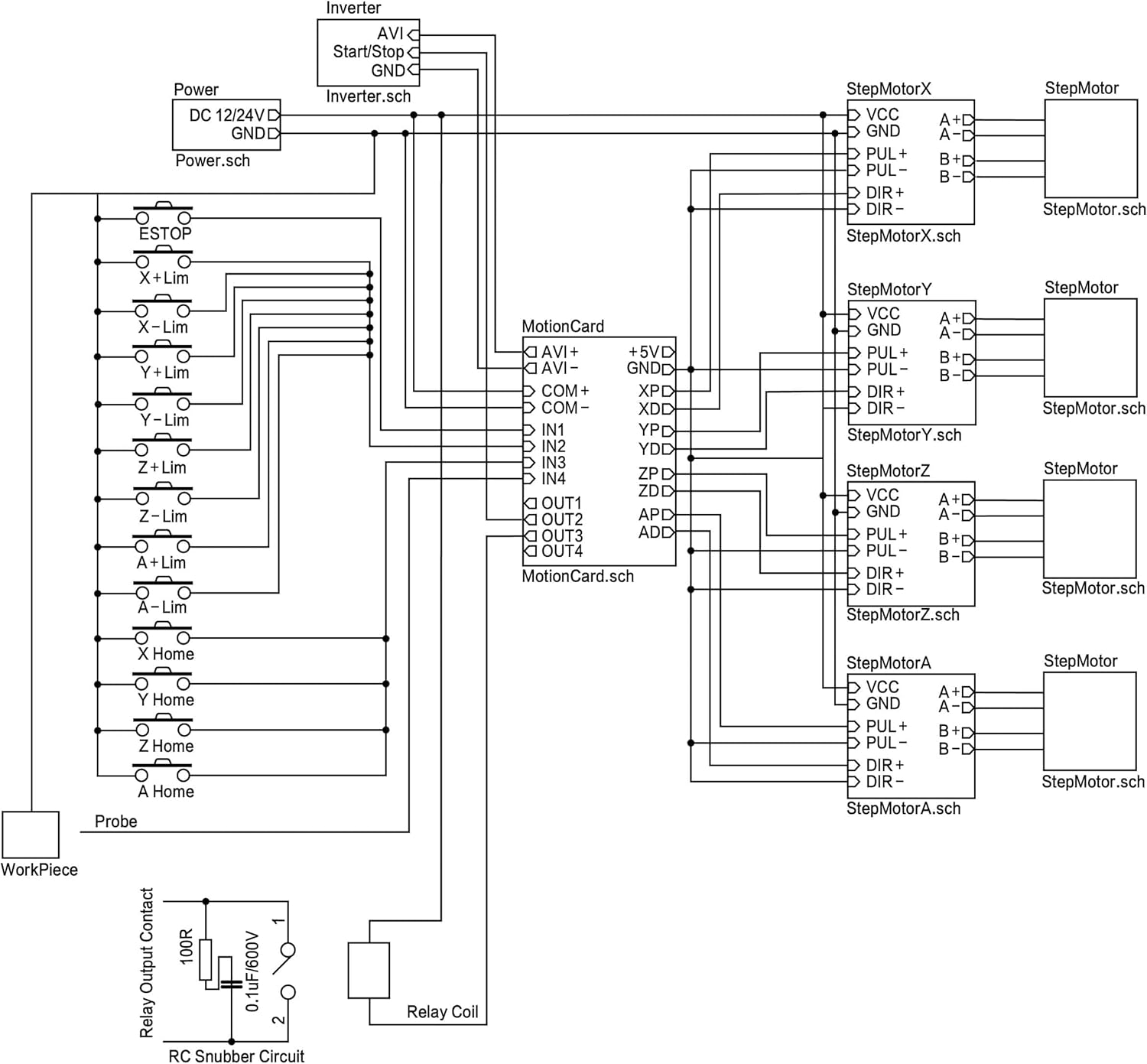
Image 5.2: Detailed wiring diagram showing connections for motors, drivers, control board, power supplies, E-stop, limit switches, and probe.

Image 5.3: Conceptual diagram illustrating the overall system connections including input devices and spindle control.
Important Safety Note:
Always ensure all power is disconnected before making or changing any wiring connections. Incorrect wiring can damage components or cause electrical hazards.
6. Software Installation and Configuration (Mach3)
The kit includes a CD with the Mach3 software. If your computer lacks an optical drive, you may need an external USB CD-ROM drive to install the software. The control board is designed to work with Mach3 without requiring additional drivers.
- Install Mach3 software from the provided CD onto a compatible Windows operating system (Windows 2000/XP/7/8/10).
- Once Mach3 is installed, connect the USB Mach3 Control Board to your PC via the USB cable.
- Launch Mach3. The control board should be recognized automatically.
- Configure Mach3 settings according to your specific CNC machine setup. This includes motor tuning, input/output pin assignments for limit switches, E-stop, and probe, and general system parameters. Refer to the Mach3 documentation for detailed configuration steps.
Tip:
Many online resources and communities offer guidance for Mach3 configuration. Searching for 'Mach3 configuration guide' or 'Mach3 setup for USB controller' can provide helpful tutorials.
7. Operating Instructions
After successful installation and configuration of hardware and software, you can begin operating your CNC machine.
- Ensure all power connections are secure and correct.
- Turn on the power supplies.
- Launch Mach3 on your computer.
- Load your G-code file into Mach3.
- Perform a machine homing sequence if configured.
- Set your workpiece zero points.
- Initiate the machining process. Monitor the machine closely during operation.
- In case of any emergency, press the E-stop button immediately.
8. Maintenance
Regular maintenance ensures the longevity and optimal performance of your RATTMMOTOR CNC kit.
- Keep Components Clean: Regularly clean dust and debris from motors, drivers, and the control board. Dust can impede heat dissipation and lead to component failure.
- Check Connections: Periodically inspect all wiring connections for looseness or damage. Tighten any loose terminals.
- Ensure Proper Ventilation: Make sure the power supplies and motor drivers have adequate airflow to prevent overheating. The 400W 36V power supply features a shell hollow design for heat dissipation.
- Software Updates: Keep your Mach3 software updated as recommended by the software provider.

Image 8.1: 400W 36V Power Supply highlighting its cooling features.
9. Troubleshooting
This section addresses common issues you might encounter.
9.1. Motors Not Moving or Moving Erratically
- Check Wiring: Verify all motor and signal wires are correctly connected and secure. Incorrect wiring (A+/A-/B+/B-) is a common cause.
- Power Supply: Ensure both 36V and 24V power supplies are on and providing correct voltage. Check the input voltage selector on the 36V supply.
- Driver Settings: Confirm the DM556S driver DIP switch settings for current and microstepping match your motor and desired performance.
- Mach3 Configuration: Review Mach3 motor tuning settings (steps per unit, velocity, acceleration) and pin assignments for pulse/direction signals.
- Emergency Stop/Limit Switches: Ensure E-stop is not engaged and limit switches are not triggered. Mach3 will prevent movement if these safety features are active.
9.2. Mach3 Software Issues
- USB Connection: Ensure the USB cable is securely connected between the control board and the PC. Try a different USB port.
- Software Installation: Reinstall Mach3 if issues persist. Ensure your operating system is compatible.
- CD Drive: If you encountered issues installing from the CD, ensure your CD-ROM drive (internal or external) is functioning correctly.
9.3. Overheating Components
- Drivers: Ensure drivers have adequate ventilation. Reduce motor current settings if possible without affecting performance.
- Power Supplies: Verify power supplies are not obstructed and their fans (if present) are operating.
10. Safety Information
- Always disconnect power before performing any maintenance or wiring changes.
- Ensure proper grounding for all electrical components.
- Install and test an emergency stop button for immediate shutdown in critical situations.
- Keep hands and loose clothing away from moving parts of the CNC machine during operation.
- Operate the kit in a well-ventilated area to prevent overheating.
- If you are unsure about any wiring or setup steps, consult a qualified electrician or experienced CNC technician.
11. Warranty and Support
For warranty information or technical support, please refer to the documentation included with your purchase or contact RATTMMOTOR customer service directly through the retailer where the product was purchased. Please have your model number (3-Axis-USB-Mach3-B) and purchase details ready when contacting support.
12. Product Video
Watch this video for a visual overview of the RATTMMOTOR 3-Axis Nema23 Stepper Motor Driver USB MACH3 CNC Kit components.
Video 12.1: Overview of the 3-Axis Nema23 Stepper Motor Driver USB MACH3 CNC Kit components.


