1. Introduction
This manual provides essential information for the safe and effective installation, operation, and maintenance of the DEWIN 2P 40KA DC 1000V Photovoltaic Surge Arrester. This device is designed to protect DC photovoltaic (PV) systems from overvoltage events caused by lightning strikes and other transient surges. Adherence to these instructions is crucial for optimal performance and safety.
2. Safety Information
WARNING: Electrical shock hazard. Installation and maintenance should only be performed by qualified personnel.
- Always disconnect power to the PV system before installing or servicing the surge arrester.
- Ensure proper grounding according to local electrical codes and standards.
- Do not operate the device if it appears damaged.
- Wear appropriate personal protective equipment (PPE) when working with electrical systems.
- The device is designed for DC photovoltaic systems only. Do not use in AC systems or other applications.
3. Product Features
The DEWIN Photovoltaic Surge Arrester offers robust protection and user-friendly features:
- Application: Designed for lightning protection of Class C and Class D, providing potential equalization and rapid response to protect electrical systems and appliances from lightning and instantaneous overvoltage.
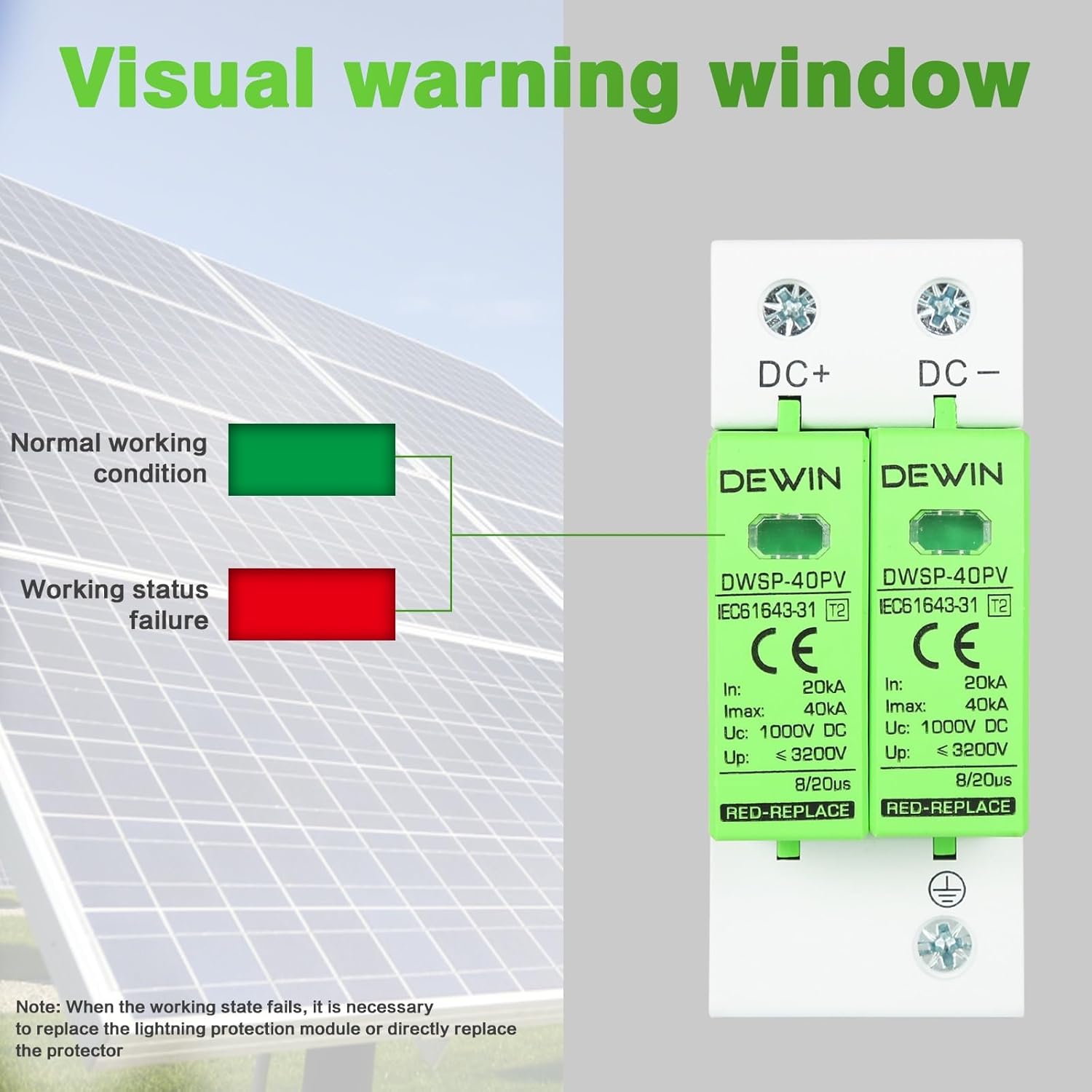
- Visual Warning Window: Features an arc-shaped design with a clear visual indicator. A green window indicates normal operation, while a red window signifies a fault condition, requiring module replacement.
- High-Quality Materials: Connection terminals are made from highly conductive copper fittings. The outer shell is constructed from flame-retardant PC material, ensuring safety and reliability.
- Easy Installation: Designed with a standard 35mm DIN rail installation slot, making it suitable for various distribution boxes. The lightning protection modules are removable and replaceable for convenient maintenance.


4. Specifications
| Specification | Value |
|---|---|
| Brand | DEWIN |
| Model | IQAARIDYA |
| Color | White |
| Nominal Discharge Current (In) | 20 kA |
| Maximum Discharge Current (Imax) | 40 kA |
| Maximum Continuous Withstand Voltage (Uc) | 1000V DC |
| Voltage Protection Level (Up) | < 3200V |
| Response Time | 8/20µs |
| Installation | 35mm DIN Rail |
| Dimensions (L x W x H) | Approximately 10.1 x 7.5 x 4.2 cm |
| Item Weight | 233 g |

5. Setup and Installation
Follow these steps for proper installation of the surge arrester:
- Preparation: Ensure all power to the photovoltaic system is disconnected and verified with a multimeter.
- Mounting: Mount the DEWIN surge arrester onto a standard 35mm DIN rail within your distribution box. Ensure it is securely fastened.
- Wiring: Connect the DC+ and DC- terminals of the surge arrester to the corresponding positive and negative lines of your PV system. Connect the ground wire terminal to a reliable earth ground. Refer to the wiring diagram below for correct connections.
- Verification: After wiring, double-check all connections for tightness and correctness. Ensure no bare wires are exposed.
- Power On: Restore power to the PV system. Observe the visual warning window on the surge arrester. It should display green, indicating normal operation.


6. Operating Instructions
The DEWIN surge arrester operates automatically to protect your PV system from surges. Its operational status is indicated by the visual warning window:
- Green Window: Indicates that the surge arrester is functioning normally and providing protection.
- Red Window: Indicates that the surge arrester module has failed or reached its end of life due to absorbing a significant surge. The module needs to be replaced.
7. Maintenance
Regular inspection of the surge arrester is recommended to ensure continuous protection:
- Visual Inspection: Periodically check the visual warning window. If it shows red, the module requires replacement.
- Module Replacement: If a module indicates a fault (red window), disconnect power to the system. The plug-in design allows for easy removal and replacement of the faulty module. Ensure the replacement module has the same specifications. After replacement, restore power and verify the window shows green.
- Connection Check: Annually, or after any significant electrical event, check all wiring connections to ensure they are secure and free from corrosion.
8. Troubleshooting
If you encounter issues with your DEWIN surge arrester, refer to the following:
- Problem: The visual warning window is red.
Solution: This indicates the surge protection module has activated and absorbed a surge, rendering it ineffective. The module needs to be replaced. Disconnect power, remove the faulty module, insert a new module with identical specifications, and restore power. - Problem: The surge arrester does not show any indication or appears to be non-functional.
Solution: Verify that power is supplied to the system and all connections are secure. If the issue persists, consult a qualified electrician.
9. Warranty and Support
No specific warranty or support information is provided within this manual. For warranty details or technical assistance, please refer to the product packaging or contact your point of purchase.