1. Introduction and Product Overview
This manual provides comprehensive instructions for the installation, operation, and maintenance of your new The ROP Shop 3100psi 7/8" Shaft Power Pressure Washer Pump. This pump is designed for various pressure washer models, including Troy-Bilt 020641-00 and 020605-00. It features a maximum pressure of 3100 PSI and a maximum flow of 2.5 GPM, operating at 3400 RPM. The pump is a sealed unit, requiring no oil maintenance.
The pump comes with a chemical injector, unloader valve, thermal release valve, and outlet tube pre-installed, along with a keyway and chemical hose with filter.
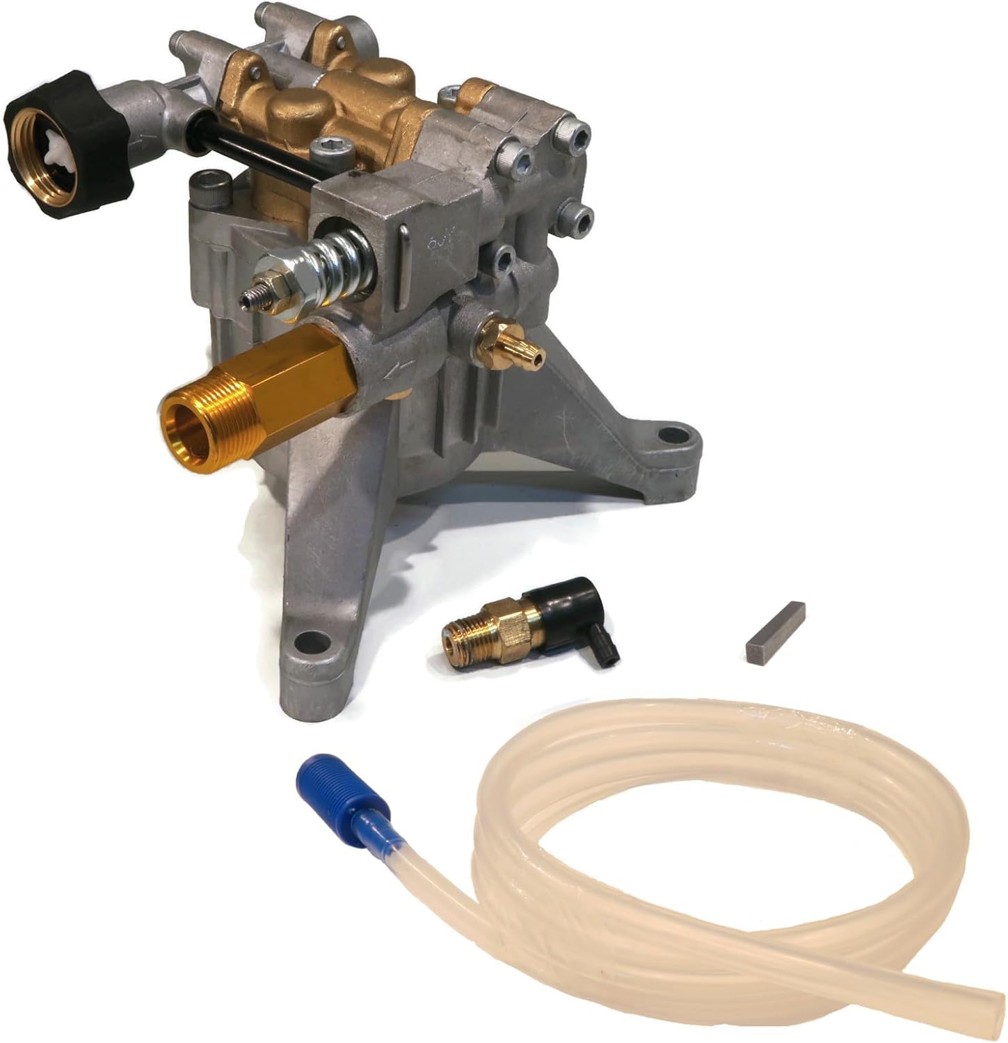
Figure 1: The ROP Shop 3100psi Pressure Washer Pump with included accessories (chemical injector, unloader valve, thermal release valve, outlet tube, keyway, and chemical hose with filter).
Video 1: Product Overview. This video provides a general overview of the 3100psi pressure washer pump.
2. Setup and Pre-Installation
2.1 Tools and Materials Needed
- Correct size wrench for pump bolts
- Allen wrench (if your unit has a set screw)
- Anti-seize compound
- Blue threadlocker liquid
- Rag and cleaning solvent
- Spacers (washers) and longer bolts (if needed for proper mounting)
2.2 Important Pre-Installation Steps
- Disconnect Spark Plug: Before beginning any work, pull the recoil start cable a couple of times and then disconnect the spark plug wire to prevent accidental starting of the motor.
- Unit Positioning: It is best to avoid laying an under-mounted pressure washer on its back. If you need to lay your vertical-mounted pressure washer on its side or back, be aware of where the oil will pool to prevent leakage. Ensure the pressure washer is in a firm, stationary position to avoid damaging the unit, the pump, or yourself.
3. Installation Guide
3.1 Removing the Old Pump
- Remove Bolts: Using the correct size wrench, remove the bolts that attach the pump to the motor.
- Check for Set Screw: In some cases, especially on 7/8" shafts that originally had a strap-style pump installed, there may be an additional set screw securing the pump to the engine shaft.
- Access Set Screw (if applicable): To gain access to the set screw, locate the open access near the shaft of the pump. Gently and slowly pull the recoil start cable; the shaft inside the access opening will spin, and you will eventually see the set screw moving into view.
- Remove Set Screw (if applicable): Using the correct size Allen wrench, remove the set screw. If the set screw falls off into the housing unit when you attempt to pull it out, you will be able to retrieve it when you pull the pump off.
- Remove Pump: The bolts and set screw (if present) are the only parts holding the pump on. You should be able to work your pump free and pull it off the engine shaft.
Troubleshooting Pump Removal
- Stuck Pump: If you find it difficult to slide the pump off, it may be corroded in the shaft allowance.
- Threaded Holes: Some pumps have threaded holes on the base of the existing pump that can be used to separate the pump from the shaft. Be careful when torquing down on the bolts so you don't damage the engine housing.
- Pry Bar: If the pump doesn't have threaded holes, you may need to try to use a pry bar to pull off the pump. It's always best to try and remove the pump by hand instead of using a tool that could damage your pressure washer.
Video 2: How to Install. This video demonstrates the complete process of removing the old pump and installing the new one.
3.2 Installing the New Pump
- Prepare Keyway Slot: For vertically mounted pumps, use the recoil cable to move the keyway slot on the engine shaft to face you.
- Dry Fit and Check for Gaps: Dry fit your new pump without the keyway. Check each leg of the pump. If there is any gap between the pump and your engine block, or if there is a metal ring between your engine block and the bolt hole that hits the bottom of the pump's flange, you will need spacers.
- Clean and Apply Anti-Seize: Clean off the shaft with a rag sprayed with cleaning solvent (do not spray directly onto the shaft to avoid damaging the oil seal). Then, apply anti-seize to the shaft and keyway. This will help hold the keyway in place. Alternatively, you can put a small dent in one side of your keyway before pushing it onto your engine shaft to help it wedge into place and prevent it from falling out. Do not use glue or adhesive.
- Install Keyway: Clean off your old keyway or set your new one in place. Do not install your new pump without a keyway, as this will cause the shaft to spin freely or catch sporadically, damaging the pump.
- Align and Slide Pump: Line up your pump to the bolt holes. If your pump has four bolts, ensure the water inlet and outlet are facing the desired direction. Ensure the keyway slot inside the pump is facing you, just like on the shaft. You should be able to spin the pump shaft allowance by hand. If you need help, you can use a wrench or other tool, but be very careful not to mar the keyway slot. Carefully slide the pump onto the shaft. It can be tricky to line up the keyway on the pump with the key on the shaft; this might take a few tries.
- Hand Tighten Bolts: Once the pump is in place, use your fingers to hand tighten the bolts. You can use the original bolts if they are still in good condition. Again, add spacers if needed to ensure a good fit.
- Tighten Bolts Evenly: Gradually pull the recoil start cable to determine if there is any binding between the engine and the pump. If there isn't any binding, you can now use your wrench to tighten down the bolts. To ensure the pump is tightened down evenly, follow the same practice you would for a car tire: after tightening one bolt, tighten the bolt on the opposite side of the pump next.
- Apply Threadlocker: You have the option of using a threadlocker liquid (e.g., Permatex Threadlocker Blue, Loctite 242, JB Weld Threadlocker) on the thread of the bolts to help protect them from working themselves loose due to vibration. Using blue threadlocker will allow you to remove the bolts again in the future with minimal effort.
- Reinstall Set Screw: Be sure to also reinstall the set screw (if applicable).
4. Operating Instructions
Your new pressure washer pump is pre-set from the factory, so you should not need to make any other adjustments for its operation. Always ensure your pressure washer has a sufficient water supply before starting the engine.
WARNING: Do not test your power washer pump without water. Doing so can destroy your bearings and is not covered under warranty.
Reattach the spark plug cable to test the unit after installation.

Figure 2: Pump Connections. Familiarize yourself with the inlet and outlet connections before operation.
5. Maintenance
This pressure washer pump is a sealed unit, meaning no oil maintenance is required for the pump itself.
- Shaft Cleaning: To prevent future corrosion issues, regularly clean off the engine shaft with a rag and cleaning solvent.
- Anti-Seize Application: When reinstalling the pump, always apply anti-seize to the shaft and keyway to facilitate future removal and prevent corrosion.
6. Troubleshooting
- Pump Difficult to Remove: If the old pump is stuck, it may be due to corrosion or a hidden set screw. Refer to section 3.1 for detailed removal steps, including using threaded holes for separation or a pry bar with caution.
- Pump Not Seating Properly / Binding: If there are gaps between the pump and the engine block, or if the engine shaft binds with the pump, spacers (washers) may be needed. Refer to section 3.2 for guidance on dry fitting and using spacers.
- Pump Not Functioning / Shaft Spinning Freely: Ensure the keyway is correctly installed on the engine shaft and aligned with the pump. A missing or improperly installed keyway will prevent the pump from functioning and can cause damage.
- Damage to Pump Legs: This typically occurs from overtightening bolts when spacers were needed but not used. Always ensure a proper fit and use spacers if necessary.
- Pump Damage from Dry Running: Operating the pump without water will destroy the bearings. Always ensure water supply before starting.
7. Specifications
| Feature | Specification |
|---|---|
| Max Pressure | 3100 PSI |
| Max Flow | 2.5 GPM |
| Max Pump Speed | 3400 RPM |
| Shaft Diameter | 7/8" Shaft |
| Bolt Pattern | 3 Bolt Pattern: 7 11/16” x 6 3/16” x 6 7/16” & 4" Center to Each Outer Hole |
| Max Water Temperature | 140° F |
| Inlet Connection Type | Standard Garden Hose |
| Outlet Tube Connection | 22mm Male |
| Chemical Hose Inner Diameter | 1/4" (6mm) |
| Chemical Hose Outer Diameter | 3/8" (9mm) |
| Chemical Hose Length | 5' |
| Chemical Hose Material | Rubber |
| Keyway Dimensions | 3/16" x 1/4" x 1 1/8" |
| Material | Metal, Brass |
| Item Weight | 7.44 Pounds |
| Product Dimensions | 9 x 7.88 x 8 inches |

Figure 3: Pump Dimensions and Specifications.

Figure 4: 3-Bolt Pattern Detail.
8. Warranty Information
The manufacturer's warranty on this pump does not cover damage resulting from improper installation or misuse. Specifically, damage caused by overtightening bolts when spacers were needed but not used, or damage from running the pump without water, is not covered and is non-returnable.
9. Support
For additional support, troubleshooting tips, or to explore other rugged outdoor products, please visit The ROP Shop store on Amazon:


