1. Product Overview
The Temank 80A Solar Charge Controller is designed to manage the power flow from your solar panels to your battery bank and DC loads. It features automatic system voltage detection (12V/24V/36V/48V), a clear LCD display, and dual USB outputs for charging small electronic devices. This controller utilizes 3-stage intelligent PWM technology for efficient and safe battery charging, extending battery life.

Figure 1: Front view of the Temank 80A Solar Charge Controller, showing the LCD screen, control buttons, USB ports, and terminal connections.
2. Safety Instructions
Please read all instructions carefully before installation and operation to ensure proper use and prevent damage or injury.
- Ensure all wiring is correctly polarized. Incorrect polarity can damage the controller and connected devices.
- Connect the battery first, then the solar panel, and finally the load. Disconnect in the reverse order.
- Install the controller indoors, away from direct sunlight, high temperatures, and water.
- Ensure adequate ventilation around the controller for proper heat dissipation.
- Use appropriate wire gauges for all connections to prevent overheating and power loss. Refer to the specifications section for recommended wire sizes.
- Do not attempt to repair or modify the controller. Contact qualified personnel for service.
- The controller is equipped with multiple protections, including reverse connection, over-temperature, overvoltage, short-circuit, and overload protection. However, proper installation is crucial.
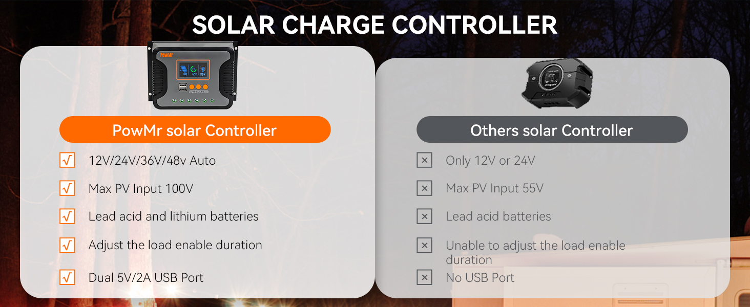
Figure 2: Overview of the controller's multiple protection features, including safeguards against reverse connection, over-temperature, overvoltage, short-circuit, and overload.
3. Setup Instructions
3.1 Mounting the Controller
Mount the solar charge controller vertically on a wall or stable surface in a well-ventilated area. Ensure there is sufficient space around the unit for air circulation. Avoid mounting near flammable materials or in areas prone to moisture.
3.2 Wiring Connections
Follow the wiring sequence carefully to prevent damage. Always connect the battery first, then the solar panels, and finally the DC load.
- Connect the Battery: Connect the positive and negative terminals of the battery to the corresponding battery terminals on the controller. Ensure correct polarity. The controller will automatically detect the system voltage.
- Connect the Solar Panels: Connect the positive and negative terminals of your solar panel array to the corresponding PV terminals on the controller. Ensure correct polarity.
- Connect the DC Load: Connect the positive and negative terminals of your DC load to the corresponding load terminals on the controller.
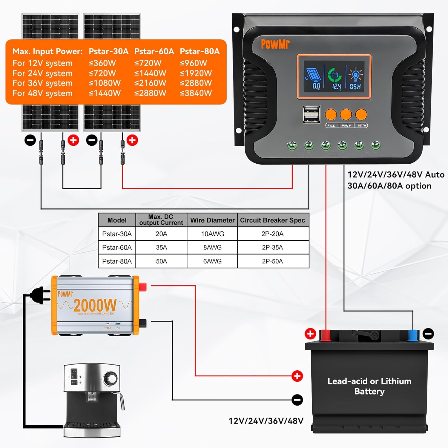
Figure 3: Detailed wiring diagram illustrating the connection sequence for solar panels, battery, and DC loads to the charge controller.
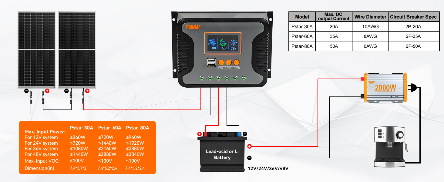
Figure 4: Simplified 2-step connection guide, emphasizing the correct order of connecting components to the solar charge controller.
4. Operating Instructions
4.1 LCD Display and Buttons
The controller features an LCD display that shows real-time system status and parameters. Three buttons are used for navigation and setting adjustments:
- PV/A Button: Used to view solar panel current and navigate menus.
- BAT/V Button: Used to view battery voltage and navigate menus.
- SET/O Button: Used to enter settings mode and confirm selections.
The display will automatically return to the default screen after 100 seconds of inactivity.
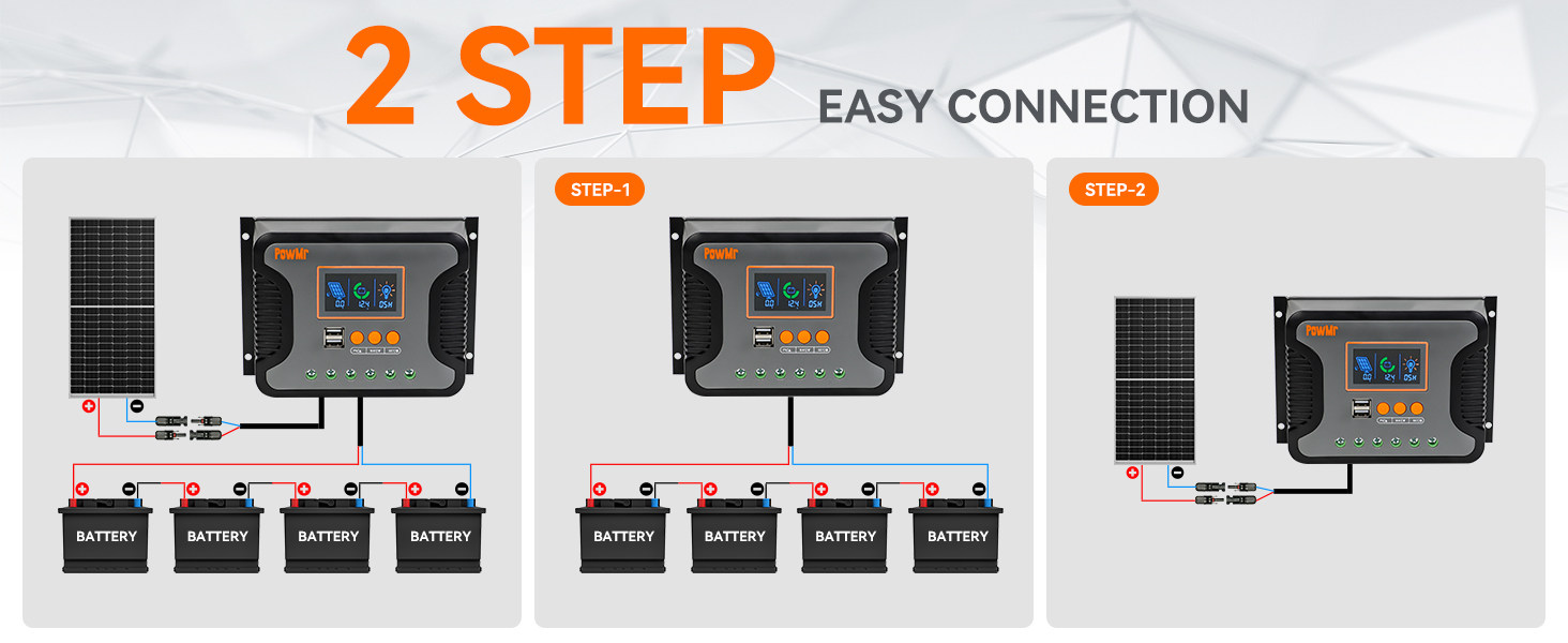
Figure 5: Detailed view of the LCD display, control buttons, USB ports, and the die-cast aluminum construction for heat dissipation.
4.2 Battery Type Selection
The controller is compatible with various 12V/24V/36V/48V battery types. It supports user-defined battery parameters and can calibrate battery voltage.
- Supported Battery Types: Sealed, Flooded, Gel, LiFePO4, and Ternary Lithium batteries.
- To select the battery type, enter the settings menu using the SET/O button and navigate to the battery type option.
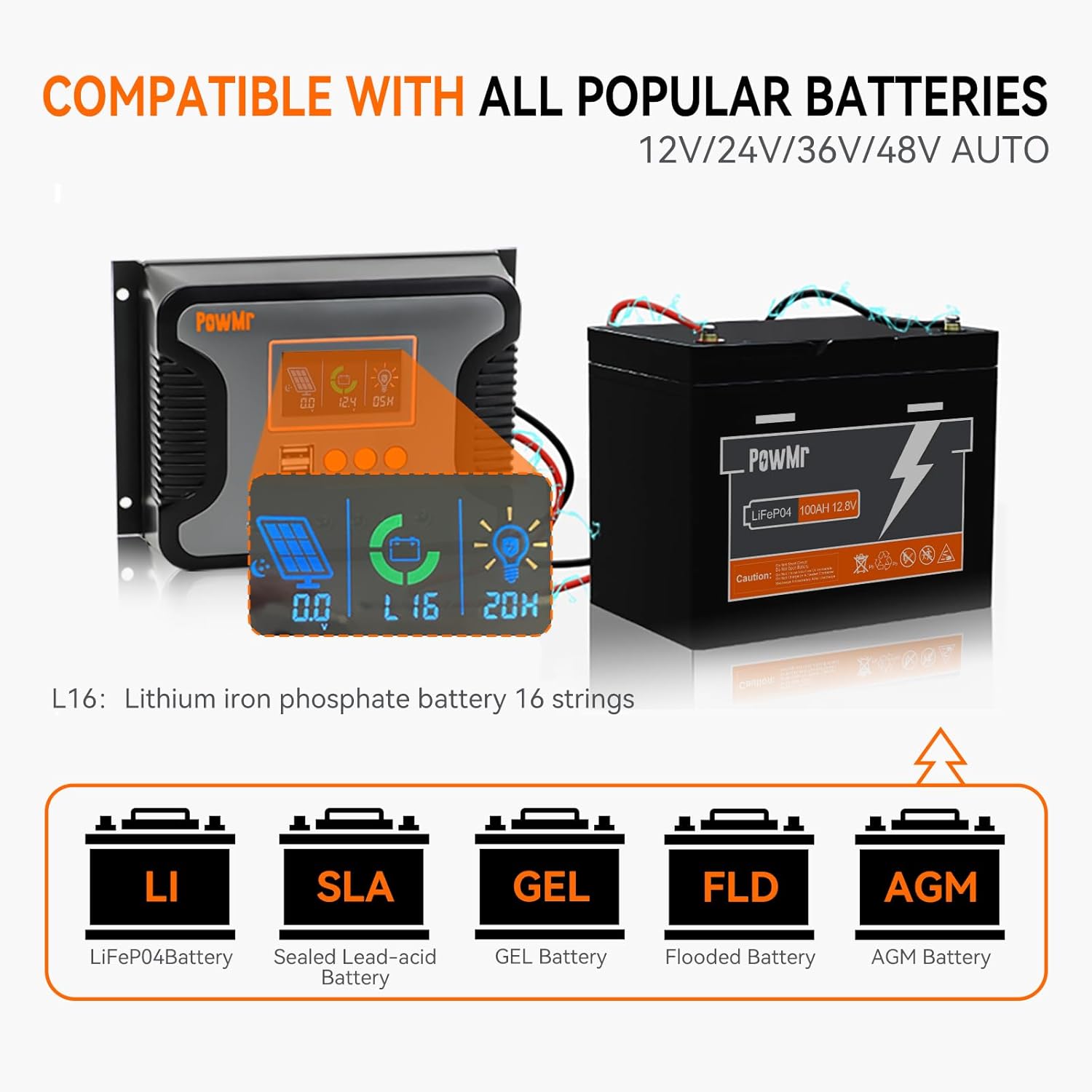
Figure 6: Visual representation of the controller's compatibility with different battery chemistries, including LiFePO4, Sealed Lead-acid, GEL, Flooded, and AGM.
4.3 Load Control and USB Output
The controller allows for adjustable load enable duration, combining solar light control and time control functions. It also features dual USB outputs (5V/2.5A max) for charging mobile phones, tablets, and other small USB-powered devices.
5. Maintenance
Regular maintenance ensures optimal performance and longevity of your solar charge controller.
- Inspection: Periodically inspect all wiring connections for tightness and corrosion.
- Cleaning: Keep the controller clean and free from dust. Use a dry cloth to wipe the surface. Do not use liquid cleaners.
- Ventilation: Ensure that the ventilation openings are not blocked to allow for proper heat dissipation.
- Environmental Conditions: Verify that the operating environment remains within the specified temperature and humidity ranges.
6. Troubleshooting
This section addresses common issues you might encounter with your solar charge controller.
- No Display/No Power:
- Check battery connections and ensure they are secure and correctly polarized.
- Verify battery voltage is within the controller's operating range.
- Battery Not Charging:
- Check solar panel connections and polarity.
- Ensure solar panels are receiving adequate sunlight.
- Verify solar panel open circuit voltage (Voc) is within the controller's maximum input voltage.
- Check for any error codes on the LCD display and refer to the manual's error code section (if available in full manual).
- Load Not Working:
- Check load connections and polarity.
- Ensure the battery has sufficient charge. The controller may disconnect the load if battery voltage is too low.
- Check load settings on the controller (e.g., light control, time control).
- Verify the load current does not exceed the controller's rated output current.
- Overheating:
- Ensure the controller is mounted in a well-ventilated area.
- Check for obstructions around the heat sink.
- Reduce load or solar input if consistently overheating in extreme conditions.
7. Specifications
Technical specifications for the Temank 80A Solar Charge Controller.

Figure 7: Key technical specifications for the 80A solar charge controller.
| Feature | Specification |
|---|---|
| Model | 80A |
| System Voltage | 12V/24V/36V/48V Auto |
| Max. PV Input Open Circuit Voltage | 100V |
| Rated Charging Current | 80A |
| Rated DC Output Current | 50A |
| Max. PV Input Power (12V Battery) | 960W |
| Max. PV Input Power (24V Battery) | 1920W |
| Max. PV Input Power (36V Battery) | 2880W |
| Max. PV Input Power (48V Battery) | 3840W |
| Charging Technology | PWM (3-Stage) |
| USB Output | Dual 5V/2.5A (max) |
| Self-consumption | ≤20mA |
| Operating Temperature Range | -20°C to +55°C |
| Item Weight | 1.54 pounds (0.7 kg) |
| Package Dimensions | 8.23 x 5.63 x 3.03 inches |
8. Warranty and Support
For warranty information and technical support, please refer to the documentation included with your purchase or contact Temank customer service through their official channels. Keep your purchase receipt for warranty claims.


