
1. Introduction
This manual provides essential information for the safe and effective installation, operation, and maintenance of your RWRAPS Din Rail ATS Dual Power Automatic Transfer Switch. Please read this manual thoroughly before installation and operation to ensure proper functionality and safety.
The RWRAPS ATS is designed to automatically switch between two power sources, typically city power and a generator, ensuring an uninterrupted power supply to your load. It is a PC-level switch with a transfer time of less than 8ms, preventing power interruptions during transitions.
Important Note: This device is designed for use with city power and generator systems only. It is not suitable for photovoltaic (PV) systems or inverters.
2. Safety Information
- Installation and maintenance must be performed by qualified electricians only.
- Ensure all power sources are disconnected before installation or servicing to prevent electric shock.
- Verify correct wiring and connections according to local electrical codes and this manual.
- Do not operate the switch if it appears damaged.
- The device contains live parts; avoid contact during operation.
- Ensure proper grounding for all connected equipment.
3. Product Overview and Features
The RWRAPS ATS is designed for reliable automatic transfer between main and backup power sources. Key features include:
- Automatic Operation: Seamlessly switches power sources without manual intervention.
- Rapid Transfer: Ensures power continuity with a transfer time of less than 8 milliseconds.
- High Conductivity: Utilizes silver contacts for enhanced conductivity and extended product lifespan.
- Signal Output Port: Built-in port for connecting signal indicator lights, allowing for convenient status observation.
- Durable Construction: Features good insulation, high temperature resistance, and anti-aging properties for reliable and safe operation.
- DIN Rail Mounting: Designed for easy installation on standard DIN rails.
Product Views
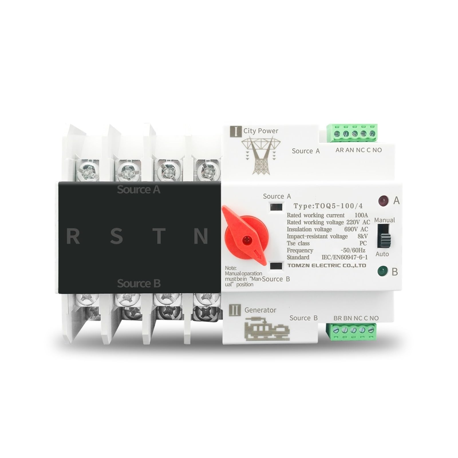


4. Specifications
| Parameter | Value |
|---|---|
| Brand | RWRAPS |
| Model Series | TOQ5 (63A, 100A, 125A variants) |
| Pole Configurations | 2P, 3P, 4P |
| Operation Mode | Automatic |
| Transfer Time | Less than 8ms (PC Level) |
| Rated Working Current | 63A, 100A, 125A (depending on model) |
| Rated Working Voltage | 220V AC (2P), 400V AC (3P, 4P) |
| Insulation Voltage | 690V AC |
| Impact-Resistant Voltage | 8kV |
| Tse Class | PC |
| Frequency | 50/60Hz |
| Standard | IEC/EN60947-6-1 |
| Mounting Type | DIN Rail |
| Contact Material | Silver |
| Item Weight | Approximately 2.2 pounds (varies by model) |
5. Setup and Installation
Before You Begin: Ensure all power is disconnected from both the main utility and the generator. Use appropriate personal protective equipment (PPE).
- Mounting: Securely mount the RWRAPS ATS onto a standard DIN rail within an electrical enclosure. Ensure adequate ventilation and clearance around the device.
- Wiring Main Power (Source A):
- Connect the main utility power (City Power) to the "Source A" terminals on the ATS.
- Ensure correct phase sequence (L1, L2, L3 for 3P/4P models) and neutral connection (N for 2P/4P models).
- Wiring Backup Power (Source B):
- Connect the generator power to the "Source B" terminals on the ATS.
- Maintain consistent phase sequence and neutral connection with Source A.
- Wiring Load:
- Connect the electrical load (circuits to be powered) to the "Load Side" terminals of the ATS.
- Signal Indicator Connection (Optional): If desired, connect external signal indicator lights to the built-in standby opening signal output port for remote status monitoring. Refer to the wiring diagram on the device for specific terminal identification.
- Verification: Double-check all wiring connections for tightness and correctness. Ensure no loose strands or exposed wires.
Warning: Incorrect wiring can lead to equipment damage, fire, or severe injury. Consult a professional electrician if you are unsure about any step.
6. Operating Instructions
The RWRAPS ATS offers both automatic and manual operation modes.
6.1 Automatic Mode
- Ensure the selector switch on the front of the ATS is set to the "Auto" position.
- Restore power to Source A (City Power). The ATS will automatically detect the presence of power and switch the load to Source A. The "A" indicator light will illuminate.
- If Source A power fails, the ATS will automatically detect the loss and, after a brief delay, switch the load to Source B (Generator Power), provided Source B is active. The "B" indicator light will illuminate.
- When Source A power is restored, the ATS will automatically switch the load back to Source A after a pre-set delay, ensuring priority for the main power source.
6.2 Manual Mode
Manual operation is typically used for testing or in situations where automatic transfer is not desired.
- Set the selector switch on the front of the ATS to the "Manual" position.
- In manual mode, you can manually rotate the switch to select either "Source A" or "Source B" to power the load.
- Caution: When operating in manual mode, ensure that the selected power source is stable and capable of handling the load. Always return to "Auto" mode for normal operation.
Note: Manual operation must be in the "Man" position as indicated on some models (refer to Figure 3.2, 3.3, 3.4).
7. Maintenance
The RWRAPS ATS is designed for minimal maintenance. However, periodic checks are recommended to ensure optimal performance and safety.
- Visual Inspection (Annually):
- Inspect for any signs of physical damage, discoloration, or overheating.
- Check for loose connections or corrosion on terminals.
- Ensure the DIN rail mounting is secure.
- Cleaning:
- Keep the device clean and free from dust and debris. Use a dry, soft cloth for cleaning.
- Do not use liquid cleaners or solvents.
- Functional Test (Periodically):
- Simulate a power outage from Source A to verify automatic transfer to Source B.
- Restore Source A power to confirm automatic transfer back.
- Test manual operation by switching between Source A and Source B.
Warning: Always disconnect power before performing any maintenance that requires touching internal components.
8. Troubleshooting
| Problem | Possible Cause | Solution |
|---|---|---|
| No power to load in Auto mode. | Both Source A and Source B are off, or one source is off and the other is not properly connected/active. | Verify power supply to both Source A and Source B. Check circuit breakers and generator operation. Ensure ATS is in "Auto" mode. |
| ATS does not switch automatically. | Selector switch is in "Manual" position, or a power source is not detected. | Set selector switch to "Auto". Check power input to both sources. Inspect wiring for loose connections. |
| Indicator light for active source is off. | Faulty indicator light or no power to that source. | Verify power to the corresponding source. If power is present, the indicator light may need replacement (contact support). |
| Device feels hot during operation. | Overload, loose connections, or inadequate ventilation. | Reduce load if exceeding rated current. Tighten all terminal connections. Ensure proper airflow around the device. If problem persists, disconnect power and contact support. |
9. Warranty and Support
For warranty information or technical support, please contact your retailer or the manufacturer directly. Keep your purchase receipt as proof of purchase.
Manufacturer: RWRAPS
Please refer to the product packaging or the seller's information for specific contact details and warranty terms.