1. Introduction
This manual provides essential information for the proper installation, operation, and maintenance of the Vbestlife 9W1077 9G7641 Ignition Starter Switch. This switch is designed as a replacement for various applications, including PS 150C, PS 500, and SR4 models. It functions as a heat start switch, activating the heat source before the engine reaches a cold temperature, which helps prevent engine damage and ensures safe operation.
The ignition switch serves as a direct replacement for old or damaged accessories, facilitating repairs and refits. Its design aims for convenience and efficiency, contributing to the normal operation of your vehicle or equipment.
2. Safety Information
- Always disconnect the battery before installing or servicing electrical components to prevent electrical shock or short circuits.
- Ensure the replacement switch matches the specifications of the original part.
- Consult a qualified technician if you are unsure about any installation steps.
- Wear appropriate personal protective equipment (PPE) such as gloves and eye protection during installation.
- Do not modify the switch or its wiring. Unauthorized modifications can lead to malfunction or damage.
3. Product Overview
The Vbestlife 9W1077 9G7641 Ignition Starter Switch is a robust component designed for reliable engine starting. It features a durable metal construction and clearly marked terminals for connection.

Figure 3.1: The Vbestlife 9W1077 9G7641 Ignition Starter Switch. This image shows the switch with a road roller in the background, illustrating its application in heavy machinery. The switch is designed to initiate the heat source before engine start-up in cold conditions.

Figure 3.2: Ignition Switch as a replacement part. This image displays the switch with a generator in the background, emphasizing its role as a direct replacement for repairing and refitting existing systems, ensuring normal operation.

Figure 3.3: The ignition switch in context. Another view of the switch with a road roller, highlighting its robust construction suitable for demanding environments.
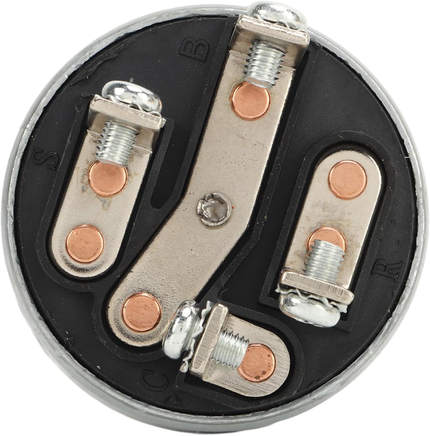
Figure 3.4: Bottom view of the switch. This image clearly shows the terminal connections labeled B, S, R, and C, which are crucial for correct wiring during installation.
4. Setup and Installation
Proper installation is crucial for the safe and effective operation of the ignition starter switch. Follow these general steps:
- Preparation: Ensure the vehicle or equipment is turned off and the battery is disconnected. Identify the location of the existing ignition switch.
- Removal of Old Switch: Carefully disconnect the wiring from the old switch, noting the position of each wire (e.g., Battery, Start, Run, Accessory). It is recommended to label each wire before removal.
- Mounting the New Switch: Insert the new Vbestlife 9W1077 9G7641 switch into the mounting hole. Secure it with the provided nut and washer, ensuring it is firmly seated.
- Wiring Connections: Connect the wires to the corresponding terminals on the new switch. Refer to the terminal labels (B, S, R, C) on the switch's base for correct connection.
- B (Battery): Connects to the main power supply from the battery.
- S (Start): Connects to the starter solenoid.
- R (Run/Ignition): Connects to the ignition system and other accessories that operate when the engine is running.
- C (Accessory): Connects to accessories that operate when the switch is in the accessory position.
- Final Check: Double-check all connections to ensure they are secure and correctly wired. Reconnect the battery.

Figure 4.1: Detailed view of the switch terminals. This image provides a clear look at the screw terminals, essential for accurate wiring during installation.

Figure 4.2: Angled view of the switch. This perspective helps in understanding the overall structure and the arrangement of the terminals for wiring.
5. Operating Instructions
The Vbestlife 9W1077 9G7641 Ignition Starter Switch typically operates with multiple positions, controlling various functions:
- OFF Position: All electrical circuits are disconnected, and the engine is off.
- ACCESSORY (ACC) Position: Allows power to accessories (e.g., radio, lights) without turning on the engine.
- RUN (ON) Position: Provides power to the ignition system and other essential components for engine operation.
- START Position: Engages the starter motor to crank the engine. Release the switch once the engine starts; it will return to the RUN position automatically.
For cold starts, the heat start function ensures the heat source is engaged before the engine cranks, protecting the engine from damage.
6. Maintenance
The Vbestlife 9W1077 9G7641 Ignition Starter Switch is designed for durability and requires minimal maintenance. However, periodic checks can help ensure its longevity and reliable performance:
- Inspect Connections: Periodically check the wiring connections to the switch for tightness and corrosion. Loose or corroded connections can lead to intermittent operation or failure.
- Cleanliness: Keep the switch free from dirt, dust, and moisture. Use a clean, dry cloth to wipe the exterior.
- Functionality Test: Occasionally test all switch positions (ACC, RUN, START) to ensure they engage smoothly and correctly.
7. Troubleshooting
If you encounter issues with your Vbestlife 9W1077 9G7641 Ignition Starter Switch, consider the following common troubleshooting steps:
| Problem | Possible Cause | Solution |
|---|---|---|
| Engine does not crank when turning to START. | Loose or corroded battery terminals; faulty battery; wiring issue to starter; faulty starter solenoid; faulty ignition switch. | Check battery connections and charge; inspect wiring to starter and solenoid; test starter and solenoid; test ignition switch continuity. |
| No power to accessories in ACC or RUN position. | Blown fuse; wiring issue; faulty ignition switch. | Check relevant fuses; inspect wiring for breaks or shorts; test ignition switch for continuity in ACC/RUN positions. |
| Engine cranks but does not start. | Fuel delivery issue; ignition system issue; engine mechanical problem. (Less likely switch related, but can be if RUN position is intermittent). | Check fuel pump, fuel filter, spark plugs, ignition coils. Ensure switch maintains power in RUN position. |
| Switch feels stiff or sticky. | Internal wear or debris. | Replacement may be necessary if cleaning does not resolve the issue. |
If problems persist after attempting these solutions, it is recommended to consult a professional mechanic or technician.
8. Specifications
| Feature | Detail |
|---|---|
| Model Number | VBESTLIFEdvpsg4ryht |
| Part Numbers | 9W1077, 9G7641 |
| Brand | Vbestlife |
| Manufacturer | VBESTLIFE |
| International Protection Rating | IP00 |
| ASIN | B0CBS877YB |
| Compatibility | Universal replacement for PS 150C, PS 500, SR4, and similar applications. |
9. Warranty and Support
For warranty information or technical support regarding your Vbestlife 9W1077 9G7641 Ignition Starter Switch, please refer to the documentation provided with your purchase or contact the retailer/manufacturer directly. Keep your proof of purchase for warranty claims.


