
1. Product Overview
This manual provides instructions for the LAPOND 20HP 15KW Variable Frequency Drive (VFD) Inverter, designed to convert single-phase 220V AC power to three-phase 220V AC power for controlling the speed of 3-phase AC motors. This series features high-performance vector control for stable operation and high torque at low speeds, enhancing motor efficiency.
Key Features:
- High-performance vector control for stable operation and high torque at low speeds.
- Support for external braking resistors and external potentiometers.
- Rich digital and analog control terminals for versatile control options.
- RS485 communication port with standard international MODBUS main circuit control.
- Strong anti-jamming capability for reliable use.
- User-friendly keyboard design with a clear digital display.
- Detachable operation panel for convenient remote control.
- Efficient heat dissipation design for extended service life.
2. Safety Information
Read and understand all safety instructions before installation, operation, or maintenance of the VFD. Failure to comply with these instructions may result in serious injury or equipment damage.
- Electrical Hazard: This VFD operates with high voltage. Only qualified personnel should perform installation and maintenance. Ensure power is disconnected and verified before touching any terminals.
- Grounding: Always ensure the VFD and the motor are properly grounded to prevent electric shock.
- Overcurrent Protection: Install appropriate overcurrent protection devices (e.g., circuit breakers) on the input power line.
- Environmental Conditions: Do not expose the VFD to direct sunlight, excessive dust, corrosive gases, flammable materials, or moisture. Operate within specified temperature and humidity ranges.
- Motor Compatibility: Ensure the motor's voltage and current ratings are compatible with the VFD's output.
- Emergency Stop: Implement an external emergency stop circuit for safety.
- Capacitor Discharge: Wait at least 10 minutes after disconnecting power before touching internal components, as capacitors may retain a dangerous charge.
3. Product Components and Features
3.1 Removable Operation Panel
The VFD features a removable operation panel, allowing for flexible control and monitoring. This panel can be detached for remote operation, providing convenience in various installation scenarios.

Image: The LAPOND VFD unit shown with its detachable control panel, highlighting the flexibility for remote operation and vector control capabilities.
3.2 Terminal Control
The VFD is equipped with various terminals for input, output, and control signals. These terminals facilitate connection to power sources, motors, and external control devices.

Image: A close-up view of the VFD's terminal block, illustrating the various connection points for control wiring, including +10V, GND, 485+, 485-, DI1, DI2, DI3, AI1, AI2, AO1, and COM.
3.3 Internal Design and Cooling
The VFD incorporates advanced internal components and a robust design for reliability and longevity.

Image: A composite image showing the internal structure of the VFD, highlighting the newest mainboard, full chip design for stability, flame-retardant material for safety, and a powerful cooling fan for efficient heat dissipation.
4. Setup and Installation
4.1 Mounting
Mount the VFD in a vertical position on a flat, non-flammable surface. Ensure adequate clearance around the unit for proper ventilation and heat dissipation. Avoid mounting in direct sunlight or areas with high vibration.
4.2 Wiring Diagram (4KW-15KW)
Follow the wiring diagram carefully for correct and safe installation. Ensure all connections are secure and properly insulated.
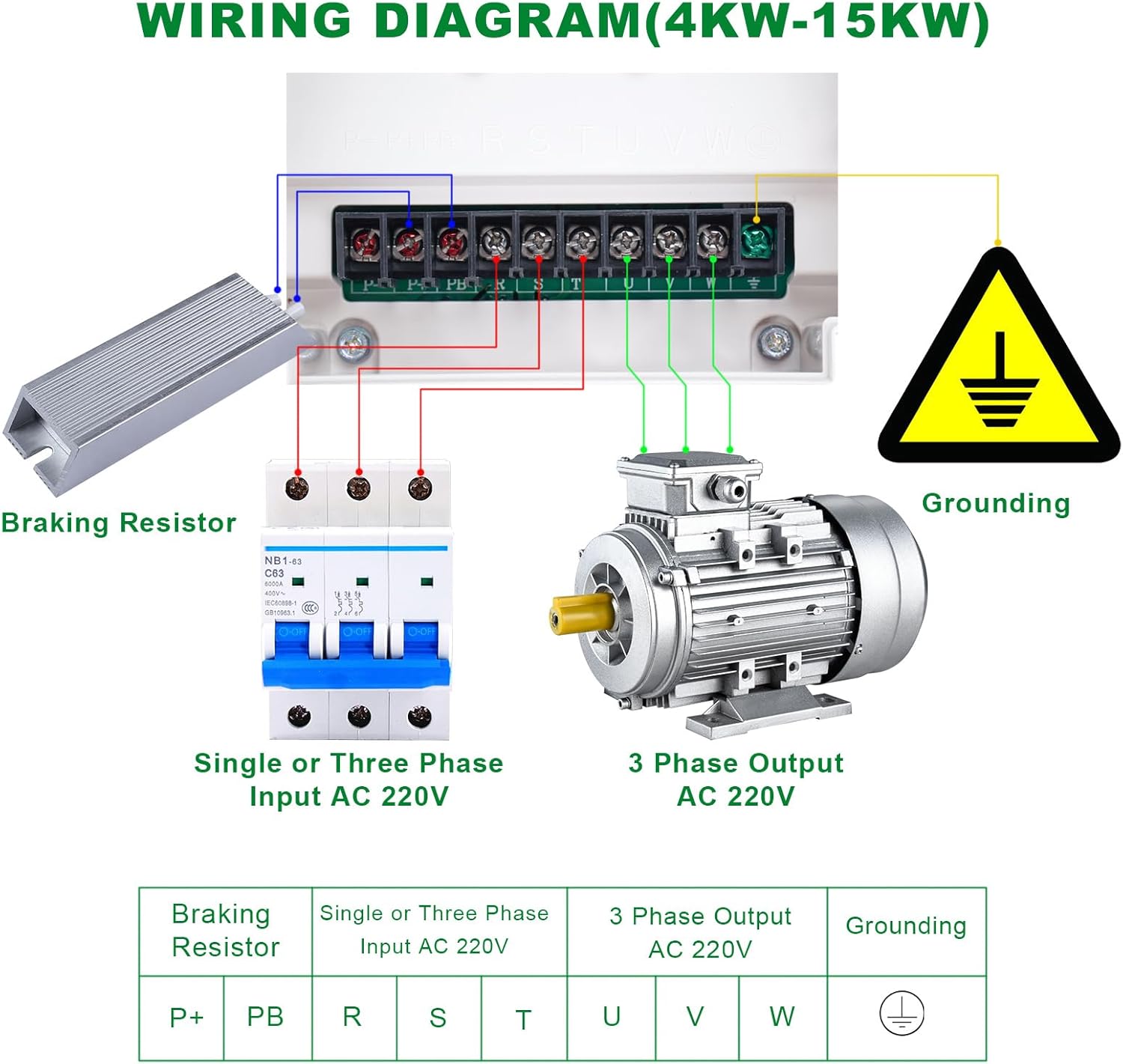
Image: A detailed wiring diagram illustrating connections for the LAPOND VFD. It shows the input (single or three-phase AC 220V) connected via a circuit breaker, the output to a 3-phase AC 220V motor, a braking resistor connection, and the grounding point.
Wiring Connections:
- Input Power (R, S, T): Connect your single-phase or three-phase 220V AC power supply to terminals R, S, and T. For single-phase input, connect the live and neutral wires to R and S (or R and T), leaving the third input terminal unused.
- Output to Motor (U, V, W): Connect the three-phase motor's input terminals to U, V, and W on the VFD.
- Grounding (⚧): Connect the VFD's grounding terminal to a reliable earth ground. Ensure the motor is also properly grounded.
- Braking Resistor (P+, PB): If an external braking resistor is used, connect it between terminals P+ and PB. This is optional and used for applications requiring rapid deceleration.
Note: Always consult local electrical codes and standards for proper wiring practices.
5. Operating Instructions
5.1 Control Panel Layout
The VFD's control panel provides an intuitive interface for operation and parameter adjustment.

Image: A close-up of the VFD's control panel, with numbered labels indicating the function of each button and knob: 1. Frequency Knob, 2. Start Key (RUN), 3. Stop/Reset Key (STOP/RESET), 4. Menu Entry or Exit (PRG), 5. Shift Key (>>), 6. Numerical Modification Key (Up Arrow), 7. Numerical Modification Key (Down Arrow), 8. Select According to Function Toggle (FUNC), 9. Confirm Parameter Key (ENTER).
Control Panel Functions:
- 1. Frequency Knob: Adjusts the output frequency (motor speed).
- 2. RUN (Start Key): Initiates motor operation.
- 3. STOP/RESET (Stop/Reset Key): Stops motor operation or clears error codes.
- 4. PRG (Menu Entry or Exit): Enters or exits the parameter setting menu.
- 5. >> (Shift Key): Shifts the cursor position during parameter modification.
- ▲ (Up Arrow - Numerical Modification Key): Increases numerical values or scrolls up through menu options.
- ▼ (Down Arrow - Numerical Modification Key): Decreases numerical values or scrolls down through menu options.
- FUNC (Function Toggle): Selects different functions or display modes.
- ENTER (Confirm Parameter Key): Confirms parameter settings or enters sub-menus.
5.2 Basic Operation
- Power On: Ensure all wiring is correct and secure. Apply power to the VFD. The display will light up.
- Set Frequency: Use the Frequency Knob (1) to set the desired output frequency. Alternatively, use the PRG button to enter the parameter menu and adjust frequency parameters digitally.
- Start Motor: Press the RUN button (2) to start the motor. The motor will accelerate to the set frequency.
- Stop Motor: Press the STOP/RESET button (3) to stop the motor. The motor will decelerate and stop.
- Parameter Adjustment: To modify advanced settings, press the PRG button (4) to enter the parameter menu. Use the Up/Down arrow keys (6, 7) to navigate, the Shift key (5) to move between digits, and the ENTER key (9) to confirm changes.
6. Maintenance
Regular maintenance ensures optimal performance and extends the lifespan of your VFD.
- Cleaning: Periodically clean the VFD's exterior and cooling fan vents to prevent dust accumulation, which can hinder heat dissipation. Use a soft, dry cloth. Do not use liquid cleaners.
- Inspection: Regularly inspect all wiring connections for tightness and signs of wear or damage. Check for any unusual noises or odors during operation.
- Environmental Check: Ensure the operating environment remains within specified temperature and humidity limits.
- Fan Check: Verify that the cooling fan is operating correctly and not obstructed.
- Power Cycle: If the VFD is to be stored for an extended period, it is recommended to power it on for a short duration every few months to maintain capacitor health.
7. Troubleshooting
This section provides guidance for common issues. For persistent problems, contact technical support.
Common Issues and Solutions:
- VFD Does Not Power On:
- Check input power supply and circuit breaker.
- Verify all power connections are secure.
- Motor Does Not Start:
- Ensure the RUN button has been pressed.
- Check motor wiring (U, V, W) for correct connections.
- Verify VFD parameters are set correctly for the motor.
- Check for any error codes on the display.
- Error Code Displayed:
- Refer to the VFD's specific error code list (not provided in this manual, typically found in a more detailed technical guide) to identify the issue.
- Common error codes relate to overcurrent, overvoltage, undervoltage, overload, or overheating.
- Press STOP/RESET to clear the error after resolving the underlying cause.
- Motor Runs at Incorrect Speed:
- Adjust the Frequency Knob or frequency parameter settings.
- Verify the motor's rated frequency and VFD output frequency settings.
- Excessive Noise or Vibration:
- Check motor mounting and alignment.
- Ensure motor is properly grounded.
- Verify VFD parameters related to motor tuning (if applicable).
8. Specifications
| Specification | Value |
|---|---|
| Model Number | K100-015G1 |
| Brand | LAPOND |
| Power Rating | 15 KW (20 HP) |
| Input Voltage | 220VAC (+/-15%) |
| Input Phase | 1 Phase |
| Input Frequency | 50/60 Hz |
| Output Voltage | 220VAC (+/-15%) |
| Output Phase | 3 Phase |
| Output Current | 60A |
| Output Frequency | 0-400 Hz |
| Product Dimensions (L x W x H) | 20.3L x 20.3W x 32.5H Centimetres (8 x 8 x 12.8 inches) |
| Item Weight | 7.31 kg |
| Display Type | Digital |
| Recommended Uses | CNC router, milling machine, drilling machine, mixer, extruder, slitter, winder, compressor, ventilator, pump, grinder, conveyor, elevator, centrifuger, wingding machine |
9. Warranty and Support
LAPOND products are designed for reliability and performance. This product typically comes with a standard manufacturer's warranty covering defects in materials and workmanship under normal use.
For warranty claims, technical assistance, or further inquiries, please contact LAPOND customer support through your purchase platform or the official LAPOND website. Please have your model number (K100-015G1) and purchase details ready when contacting support.
10. Applications
The LAPOND VFD is suitable for a wide range of industrial and commercial applications requiring precise motor speed control.

Image: An illustration depicting various applications where the LAPOND VFD can be utilized, including pumps, CNC machines, textile machinery, industrial control panels, mining equipment, mixers, and other motor-driven systems.


