Lelukee 4-20ma 1 in 1out
Lelukee Analog Signal Isolator Transmitter Splitter User Manual
Model: 4-20ma 1 in 1out
Introduction
The Lelukee Analog Signal Isolator Transmitter Splitter is designed for industrial applications, providing isolated power distribution for field transmitters and transmitting current signals to control systems like PLCs and DCS. This device ensures high accuracy, linearity, and low temperature drift through efficient magnetic isolation technology between input, output, and power supply. It is compatible with 2-wire, 3-wire transmitters, and current sources.
Product Overview

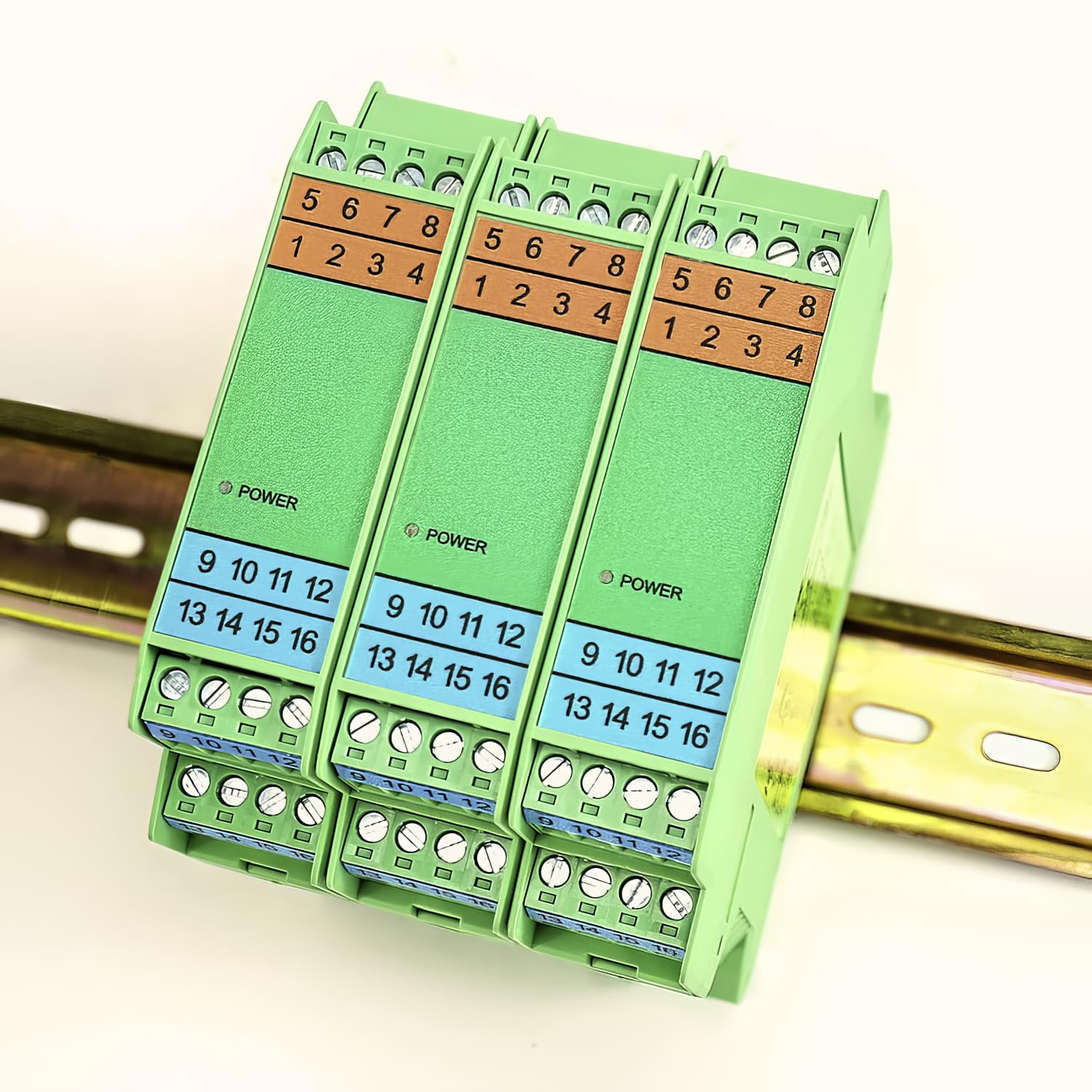

What's in the Box
The product package includes the following item:
- Signal Isolator Transmitter Splitter (1 unit)
Setup and Installation
The Lelukee Signal Isolator is designed for easy installation on a standard DIN rail. Ensure all power is disconnected before proceeding with installation and wiring.
Mounting
The device features a clip mechanism for secure attachment to a 35mm DIN rail. Simply align the bottom clip with the rail, push the unit down, and snap the top clip into place.

Wiring Connections
Refer to the wiring diagram below for proper connection of power, input, and output signals. This model is a 1-in-1-out configuration for 4-20mA signals.
- Power Supply (PWR): Connect DC 24V to terminals 15(-) and 16(+).
- Input: For 2-wire transmitters, connect to terminals 9(-) and 13(+). For 3-wire transmitters, connect to 9(+), 10(-), and 13(+).
- Output (Channel 1): Connect the 4-20mA output to terminals 1(+) and 2(-).


Operation
Once properly installed and wired, the signal isolator operates automatically. It receives the 4-20mA current signal from the field transmitter, isolates it to prevent ground loops and noise, and then transmits an identical isolated 4-20mA signal to the control system.
- Power Indicator: A green LED on the front of the unit indicates that the device is powered on.
- Signal Integrity: The internal high-efficiency magnetic isolation technology ensures the integrity and accuracy of the signal transmission, minimizing interference and maintaining high linearity.
Maintenance
The Lelukee Signal Isolator is designed for reliable, long-term operation with minimal maintenance. However, periodic checks can help ensure optimal performance:
- Visual Inspection: Periodically inspect the unit for any signs of physical damage, loose connections, or excessive dust accumulation.
- Connection Integrity: Ensure all screw terminals are securely tightened to prevent intermittent signal loss or power issues.
- Cleaning: If necessary, gently clean the exterior of the unit with a soft, dry cloth. Do not use liquid cleaners or solvents.
Troubleshooting
If you encounter issues with the signal isolator, consider the following troubleshooting steps:
- No Power Indicator:
- Check the DC 24V power supply connection to terminals 15(-) and 16(+).
- Verify the power supply is active and providing the correct voltage.
- Incorrect Output Signal:
- Verify the input signal (4-20mA) from the field transmitter is correct and stable.
- Check the output wiring to the PLC/DCS for proper connection to terminals 1(+) and 2(-).
- Ensure the load resistance is within the specified range (Load≤500Ω).
- Intermittent Signal:
- Inspect all wiring connections for looseness or damage.
- Check for sources of electromagnetic interference in the vicinity.
If problems persist after performing these checks, contact technical support for further assistance.
Specifications

| Parameter | Value |
|---|---|
| Model | 4-20ma 1 in 1out |
| Power Supply (PWR) | DC 24V |
| Input Signal | 4-20mA |
| Output Signal | 4-20mA (Channel 1) |
| Output Current Load | ≤500Ω |
| Accuracy | 0.1% FS |
| Working Temperature Range | -20℃ to +55℃ |
| Electromagnetic Compatibility | Comply with GB/T 18268 (1EC61326-1) |
| Applicable Field Equipment | 2-wire, 3-wire transmitter, current source |
| Product Dimensions (Height) | 114.5 mm (approx. 4.51 inches) |
| Product Dimensions (Depth) | 99.0 mm (approx. 3.90 inches) |
| Product Dimensions (Width) | 22.5 mm (approx. 0.89 inches) |
| Weight | Approx. 5.29 ounces (150g) |
| Mounting Type | DIN Rail |
| Number of Pins | 9 |
Warranty and Support
Specific warranty details are not provided within this manual. For information regarding warranty coverage, technical support, or service, please refer to the official Lelukee website or contact your authorized distributor.
Ask a question about this manual
Ask about setup, troubleshooting, compatibility, parts, safety, or missing instructions. Manuals+ will review the question and use this page’s manual context to help answer it.