1. Introduction
This manual provides comprehensive instructions for the installation, operation, and maintenance of the Onisamt Universal Ceiling Fan Remote Control Kit, Model RC-72T&RC-72R. This kit is designed to enhance the functionality of most 3-speed AC ceiling fans by adding convenient remote control capabilities, including fan speed adjustment, light dimming, and a time delay feature.
The kit includes a transmitter (remote control) and a receiver, allowing for wireless control of your ceiling fan and its integrated lighting. Please read this manual thoroughly before installation and use to ensure proper function and safety.
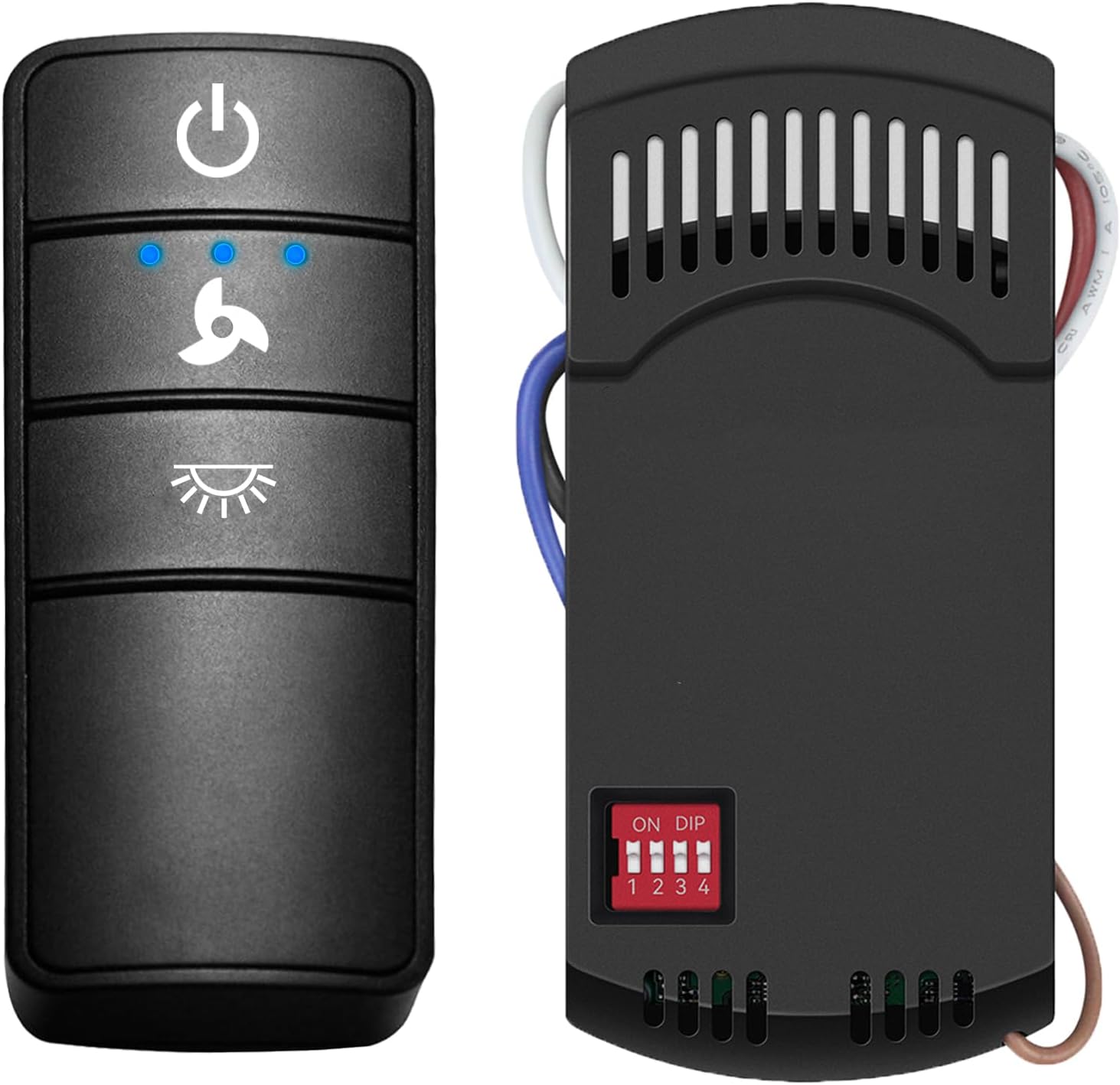
Image 1.1: Onisamt Universal Ceiling Fan Remote Control and Receiver.
2. Safety Information
Please observe the following safety precautions during installation and operation:
- Electrical Hazard: Always disconnect power at the circuit breaker or fuse box before attempting any installation, wiring, or maintenance. Failure to do so can result in serious injury or death.
- Qualified Electrician: If you are unsure about any part of the installation process, consult a qualified electrician.
- Voltage Compatibility: Ensure the ceiling fan and the remote kit are compatible with your home's electrical supply (110V-120V AC, 60Hz).
- Secure Connections: All wire connections must be secure and properly insulated using wire nuts.
- Receiver Placement: Ensure the receiver is installed within the fan canopy and does not interfere with the fan's operation or wiring.
- Battery Safety: Do not mix old and new batteries. Do not mix alkaline, standard (carbon-zinc), or rechargeable (nickel-cadmium) batteries. Dispose of used batteries properly.
3. Package Contents
Verify that all items listed below are present in your package:
- 1 x Transmitter (Remote Control)
- 1 x Receiver
- 1 x Wall Mount Holder for Remote
- 1 x User Guide (this manual)
- 6 x Wire Nuts
- 2 x Screws for Wall Mount
- Note: One 12V battery for the remote control is NOT included and must be purchased separately.

Image 3.1: Contents of the Onisamt Universal Ceiling Fan Remote Control Kit.
4. Setup and Installation
Follow these steps to install your Onisamt Universal Ceiling Fan Remote Control Kit:
4.1. Pre-Installation Steps
- Disconnect Power: Before beginning any work, ensure the power to the ceiling fan is turned off at the circuit breaker.
- Remove Canopy: Carefully remove the ceiling fan canopy to access the wiring.
- Install Remote Battery: Open the battery compartment on the back of the remote control and insert one 12V battery (not included), observing polarity.
4.2. Setting DIP Switches
Both the remote control (transmitter) and the receiver have DIP switches. These switches must be set to the same code for the remote and receiver to communicate. There are 16 possible combinations. Avoid using the default setting of '0000' (all switches down) as it may cause interference with other devices.
- Locate the DIP switches on both the remote control (inside the battery compartment) and the receiver.
- Using a small tool (like a pen tip), set the switches on both the remote and the receiver to an identical pattern. For example, if you set switches 1 and 3 up on the remote, set switches 1 and 3 up on the receiver.
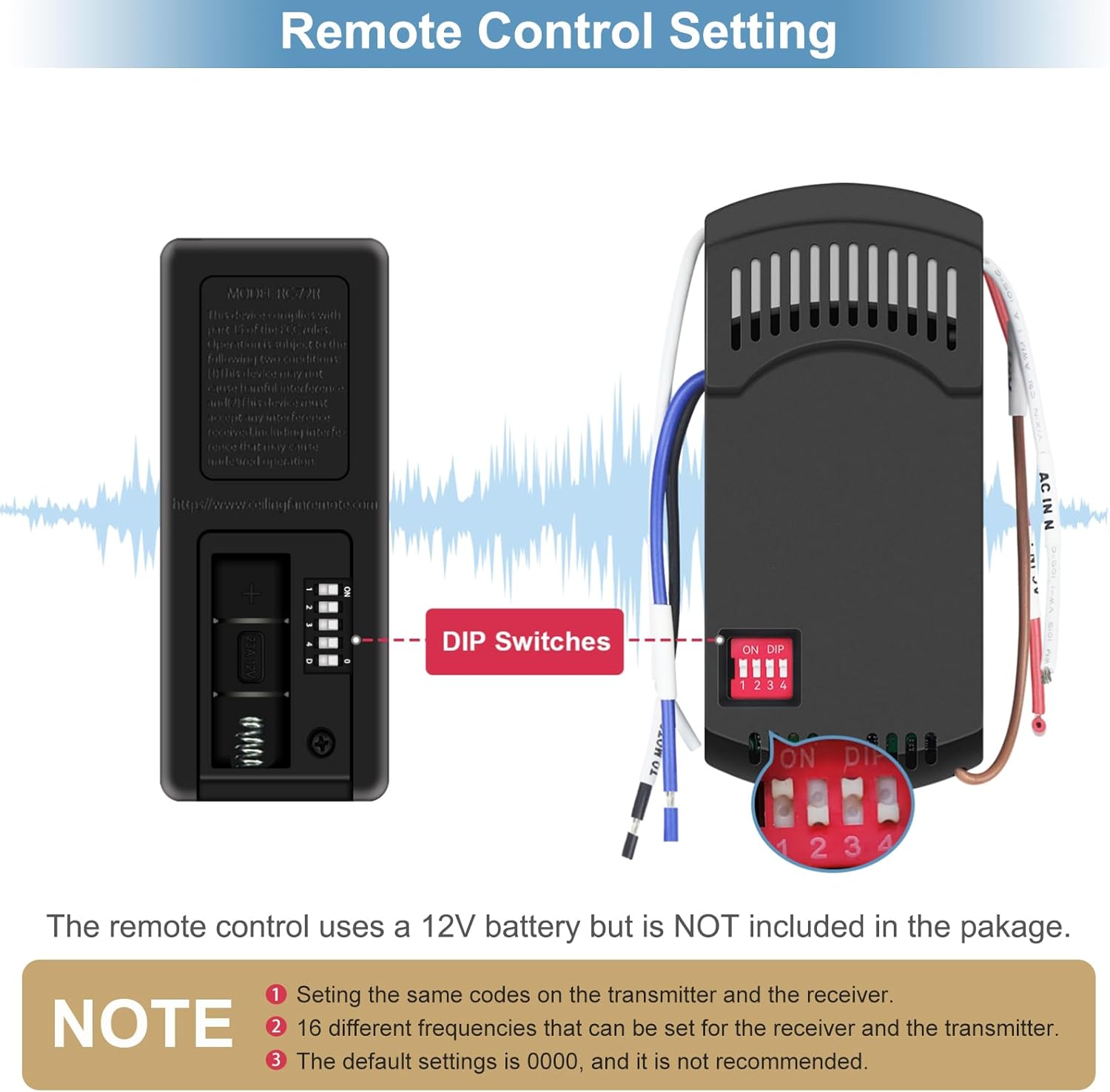
Image 4.1: Setting DIP Switches for Remote and Receiver Synchronization.
4.3. Wiring the Receiver
Refer to the wiring diagram below. Ensure all connections are secure.
- Identify Wires: Your ceiling fan will have wires for power (Live/Hot), neutral, fan motor, and light. The receiver has corresponding input and output wires.
- Connect Input Wires:
- Connect the Black (AC IN L) wire from the receiver to the Live/Hot wire from the ceiling.
- Connect the White (AC IN N) wire from the receiver to the Neutral wire from the ceiling.
- Connect Output Wires:
- Connect the Black (TO MOTOR L) wire from the receiver to the Fan Motor Live wire.
- Connect the Blue (TO LIGHT L) wire from the receiver to the Light Live wire.
- Connect the White (TO MOTOR N) wire from the receiver to the Fan Motor Neutral and Light Neutral wires (often combined).
- Secure Connections: Use the provided wire nuts to secure all connections.
- Position Receiver: Carefully tuck the receiver and all wiring into the fan canopy, ensuring no wires are pinched and the receiver is not obstructing fan movement.
- Reattach Canopy: Securely reattach the fan canopy.
- Restore Power: Turn the power back on at the circuit breaker.
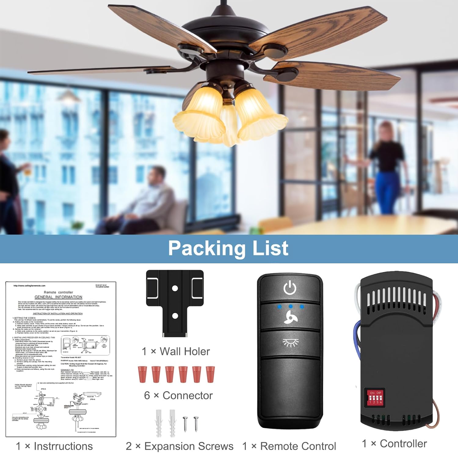
Image 4.2: Wiring Diagram for Receiver Installation.
5. Operating Instructions
The remote control provides intuitive operation for your ceiling fan and light.

Image 5.1: Remote Control in Use for Fan and Light Functions.
5.1. Remote Control Buttons
- Power Button (⏻): Turns the fan and light ON/OFF.
- Fan Speed Button (🍋): Cycles through fan speeds: High, Medium, Low, Off. Press repeatedly to change speed.
- Light Button (💡):
- On/Off: Press briefly to turn the light ON or OFF.
- Dimming: If using dimmable bulbs, press and hold the light button to dim or brighten the light. Release when the desired brightness is reached.
5.2. Light Dimming Dipswitch (O/D)
On the receiver, there is an O/D (On/Off / Dimming) dipswitch. This switch determines whether the light function is simply On/Off or if it supports dimming.
- 'O' Position (On/Off): Set to 'O' if you are using non-dimmable bulbs or prefer simple On/Off functionality.
- 'D' Position (Dimming): Set to 'D' if you are using dimmable bulbs and wish to utilize the dimming feature.
Important: This setting must be configured before installation or by accessing the receiver within the fan canopy.
5.3. Time Delay Feature
The remote includes a walk-away time delay feature for the light. To activate:
- Press and hold the Power button (⏻). The light will turn off after approximately 30 seconds, allowing you time to exit the room before the light extinguishes.
6. Compatibility
This universal remote control kit is designed to be compatible with most major 110V 3-speed AC ceiling fans. It supports various brands, including but not limited to Hampton Bay, Harbor Breeze, Home Decorators Collection, Hunter, Litex, Honeywell, Allen+Roth, Kichler, and Westinghouse.
The remote control is compatible with fan remotes having FCC ID / Model numbers such as 98130, KUJCE10318, 2AAZPHD3/HD3, KUJCE10320/TR222A, KUJCE10712, KUJCE10716, KUJCE10311, and KUJST18003.
6.1. Light Bulb Compatibility
The light control function supports various lamp types:
- Halogen & Incandescent Lamps: Up to 4.2A / 500W Max.
- Dimmable CFL: Up to 1.5A / 150W Max.
- Dimmable LED: Up to 1.5A / 150W Max.
Note: Some LED and CFL lamps are not dimmable and will only support ON and OFF functions, even if the receiver's O/D switch is set to 'D'. Always verify your bulb's dimmability.

Image 6.1: Light Bulb Compatibility Information.
7. Maintenance
Regular maintenance helps ensure the longevity and optimal performance of your remote control kit.
- Cleaning: Wipe the remote control and receiver (if accessible) with a soft, dry cloth. Do not use abrasive cleaners or solvents.
- Battery Replacement: Replace the 12V battery in the remote control when its range decreases or the indicator light dims. Ensure proper polarity when inserting the new battery.
- Environmental Conditions: Avoid exposing the remote control or receiver to extreme temperatures, high humidity, or direct sunlight.
8. Troubleshooting
If you encounter issues with your Onisamt Universal Ceiling Fan Remote Control Kit, refer to the following troubleshooting guide:
| Problem | Possible Cause | Solution |
|---|---|---|
| Fan or light does not respond to remote. |
|
|
| Light does not dim. |
|
|
| Fan operates at incorrect speed or inconsistently. |
|
|
| Remote range is poor. |
|
|
9. Specifications
- Model Number: RC-72T&RC-72R
- Brand: Onisamt
- Operation Mode: Manual (Remote Control)
- Operating Voltage: 12 Volts (for remote battery), 110-120V AC 60Hz (for receiver)
- Current Rating: 1 Amps (Receiver)
- Connectivity Protocol: RF (Radio Frequency)
- Number of Fan Speeds: 3 (High, Medium, Low)
- Light Control: On/Off, Dimming (with compatible bulbs)
- Material: Plastic
- Item Weight: Approximately 6.7 ounces (total kit)
- Package Dimensions: 5.59 x 4.45 x 2.01 inches
10. Warranty and Support
For warranty information or technical support, please contact Onisamt customer service through the retailer where the product was purchased or visit the official Onisamt website. Please have your model number (RC-72T&RC-72R) and purchase details available when contacting support.