1. Introduction
This manual provides detailed instructions for the safe and effective use of the YuqiaoTime LCR-TC1 Multi-functional TFT Backlight Transistor Tester. This device is designed for testing various electronic components including transistors, diodes, triodes, capacitors, resistors, and inductors, featuring a 1.8-inch colorful TFT display for clear readings.
2. Safety Information
Important Safety Precautions:
- Always discharge capacitors before testing. Failure to do so can damage the tester and pose a safety risk.
- Do not attempt to test components while they are connected to a live circuit.
- Ensure the tester is powered off when connecting or disconnecting components.
- Use only the provided test leads and accessories.
- Keep the device away from water and extreme temperatures.

Image: A visual warning on the tester screen indicating the necessity to discharge electronics before testing to protect the device.
3. Package Contents
Verify that all items listed below are present in your package:
- LCR-TC1 Transistor Tester
- Battery (pre-installed or separate)
- User Manual (this document)
- Type-C Charging Cable
- Test Leads (with clips)
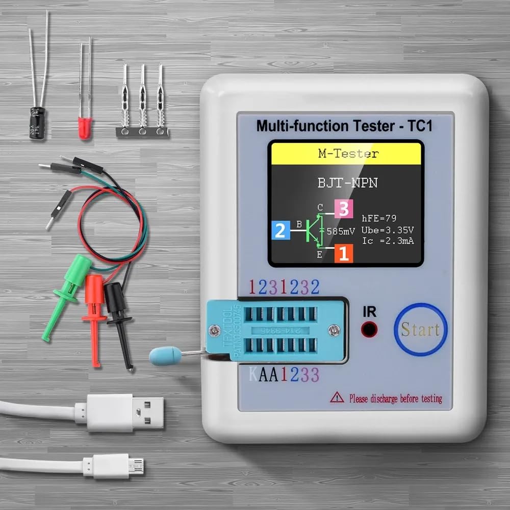
Image: The LCR-TC1 tester displayed with its various accessories, including test leads, capacitors, and a USB-C charging cable.
4. Product Overview
The LCR-TC1 is a compact and versatile multi-functional tester designed for quick and accurate identification and measurement of various electronic components. It features a 1.8-inch TFT color display for clear presentation of measurement results.
Key Features:
- Automatic detection of NPN and PNP bipolar transistors, N-channel and P-channel MOSFETs, JFETs, diodes, double diodes, thyristors, triacs, resistors, capacitors, and inductors.
- Automatic detection of pin layout.
- Measurement of current amplification factor (hFE) and base-emitter threshold voltage for bipolar transistors.
- Measurement of gate threshold voltage and gate capacitance for MOSFETs.
- Measurement of resistance with high resolution.
- Measurement of capacitance and Equivalent Series Resistance (ESR).
- Measurement of inductance.
- Automatic shutdown function to save battery life.

Image: The tester's screen displaying measurement results for an inductor, a resistor, and a capacitor, illustrating its multi-functional capabilities.
5. Setup
5.1 Charging the Battery
The LCR-TC1 is powered by a rechargeable Li-ion battery. Before first use, or when the battery indicator shows low power, connect the provided Type-C charging cable to the tester's charging port and to a standard USB power adapter (not included).
- A charging indicator will typically be displayed on the screen.
- Charging time may vary. Disconnect the charger once the battery is fully charged.
5.2 Connecting Test Leads
The tester includes a ZIF (Zero Insertion Force) socket for direct component insertion and test leads for connecting larger or wired components.
- For the ZIF socket: Lift the lever, insert the component pins into the corresponding holes (1, 2, 3), and lower the lever to secure.
- For test leads: Connect the red, green, and black test clips to the component's terminals. The tester automatically detects the pin configuration.

Image: The LCR-TC1 tester with its test clips attached to a three-pin electronic component, demonstrating external component testing.
6. Operating Instructions
6.1 Basic Testing Procedure
- Power On: Press the "Start" button to turn on the tester.
- Prepare Component: Ensure the component is discharged, especially capacitors.
- Connect Component:
- For small, unmounted components, insert pins into the ZIF socket (pins 1, 2, 3).
- For larger components or those with wires, use the provided test leads, connecting them to the component's terminals. The tester will automatically identify the connected pins.
- Start Test: Press the "Start" button again to initiate the test. The tester will automatically identify the component type and display its parameters on the screen.
- Read Results: Observe the 1.8-inch TFT display for the component type, pinout, and measured values (e.g., resistance, capacitance, hFE).
- Power Off: The tester will automatically shut down after a period of inactivity to conserve battery. You can also press and hold the "Start" button to manually power it off.

Image: The LCR-TC1 tester showing a resistor being measured, with the resistance value displayed on the screen.
6.2 Specific Component Testing Examples
- Transistors (BJT, MOSFET, JFET): The tester will identify the type (NPN/PNP, N-channel/P-channel), pinout (Base/Gate, Collector/Drain, Emitter/Source), and measure parameters like hFE, Ube, Vgs, Cgs.
- Diodes: Identifies diode type and measures forward voltage drop. For Zener diodes, it can detect Zener voltage up to 4.5V.
- Capacitors: Measures capacitance value and Equivalent Series Resistance (ESR).
- Resistors: Measures resistance value.
- Inductors: Measures inductance value and DC resistance.
7. Maintenance
- Cleaning: Use a soft, dry cloth to clean the device. Do not use abrasive cleaners or solvents.
- Storage: Store the tester in a cool, dry place away from direct sunlight and extreme temperatures.
- Battery Care: For long-term storage, ensure the battery is partially charged (around 50%) to prolong its lifespan. Recharge periodically if not used for extended periods.
- Test Leads: Inspect test leads regularly for any signs of damage. Replace if necessary.
8. Troubleshooting
- Tester does not power on:
- Check battery charge level. Recharge if necessary.
- Ensure the "Start" button is pressed firmly.
- Inaccurate readings or "Unknown component" message:
- Ensure the component is properly inserted into the ZIF socket or securely connected with test leads.
- Verify the component is not damaged.
- For capacitors, ensure they are fully discharged before testing.
- Clean component pins if they appear corroded.
- Screen is blank or flickering:
- Battery might be low. Recharge the device.
- If the issue persists, contact customer support.
9. Specifications
The following table outlines the technical specifications of the YuqiaoTime LCR-TC1 Transistor Tester:
Image: A detailed table presenting the technical parameters and specifications of the LCR-TC1 multi-functional tester.
| Parameter | Value | Parameter | Value |
|---|---|---|---|
| Display | 1.8 inch TFT Screen | Diode Range | <4.5V |
| Zener Diode Transistor Detect Area | 0.01-4.5V | Zener Diode Detect Area | 0.01-30V |
| Triac Range | IGT < 6mA | Capacitance | 25pF-100mF |
| Resistor | 0.01-50MΩ | Inductance | 0.01mH-20H |
| Battery | 0.1-4.5V | Power Mode | Li-On rechargeable |
| Item Size | 8.8x8x2.8cm / 3.46x3.15x1.10 inches | Item Weight | 111.5g / 3.94oz |
| Package Size | 14.5x12x2.7cm / 5.71x4.72x1.06 inches | Package Weight | 114g / 4.02oz |
Note: Imperial conversions for item and package size are approximate.

Image: The LCR-TC1 tester shown with its physical dimensions (91mm length, 69mm width, 28mm height) marked in millimeters.
10. Warranty and Support
For warranty information and technical support, please refer to the documentation provided at the time of purchase or contact the seller directly. Keep your purchase receipt as proof of purchase.