POWLAND ICharger-MPPT-6048
POWLAND MPPT Solar Controller User Manual
Model: ICharger-MPPT-6048
1. Introduction
This manual provides detailed instructions for the installation, operation, and maintenance of your POWLAND MPPT Solar Controller, Model ICharger-MPPT-6048. This intelligent regulator is designed to optimize the charging process from your solar panels to various battery types, ensuring efficient power conversion and battery longevity. Please read this manual thoroughly before installation and operation to ensure safe and correct usage.
2. Product Overview and Features
The POWLAND ICharger-MPPT-6048 is an advanced MPPT (Maximum Power Point Tracking) solar charge controller. It automatically detects system voltages (12V/24V/36V/48V) and is compatible with a wide range of battery types. Its robust design includes efficient heat dissipation and a multi-function LCD for easy monitoring and parameter adjustment.

Figure 2.1: Front view of the POWLAND MPPT Solar Charge Controller, showing the display and control buttons.
Key Features:
- High Charge Limit: Supports a maximum solar open circuit voltage (Voc) of 150V and a maximum solar charge current of 60Amp.
- High Efficiency: Achieves a maximum efficiency of ≥98.1% and PV utilization of ≥99%, ensuring optimal power conversion from your solar array.
- Versatile Battery Compatibility: Features automatic battery voltage detection for 12V, 24V, 36V, and 48V systems. Compatible with various battery types including lithium, LiFePO4, Li(NiCoMnO2), vacuum, alloyed, sealed, Gel, and NiCd batteries.
- Optimized Charging: Utilizes a 3-step charging process (constant current MPPT, constant voltage, floating) to optimize battery performance and extend lifespan.
- Efficient Heat Dissipation: Equipped with an intelligent cooling fan controller and an aluminum alloy heat dissipation shell to minimize energy loss and maintain optimal operating temperature.
- Multi-Function LCD Display: The programmable LCD displays various operating data and system status, allowing for quick identification of system faults and easy parameter changes.

Figure 2.2: Overview of the MPPT Solar Controller highlighting key features like multiple protection, auto voltage detection, parallel capability, and LCD display.
3. Specifications
Below are the detailed technical specifications for the ICharger-MPPT-6048 model:
| Parameter | Value |
|---|---|
| Model | ICharger-MPPT-6048 |
| Charging Mode | 3-stage: Constant Current (MPPT), Constant Voltage, Floating |
| System Voltage | 12V/24V/36V/48V Auto Recognition |
| Max PV Input Power | (720n)W (Note: 'n' likely refers to system voltage multiplier, e.g., 720W for 12V, 1440W for 24V, etc.) |
| Max PV Input Voltage | 180Voc |
| Battery Voltage Automatic Recognition | 48V Battery: DC40V-DC60V |
| Overcharging Protection Voltage | 48V Battery: 60V |
| Limited Current Protection | 61A |
| Max Efficiency | 98.1% |
| PV Utilization | 99% |
| Temperature Protection | 75℃ |
| Fan-on Temperature | >45℃ |
| Fan-off Temperature | <40℃ |
| Dimensions (mm) | 214 x 115 x 50 |
| Net Weight (Kg) | 1.1 |
| Gross Weight (Kg) | 1.2 |
| Electromagnetic Compatibility | Accord to EN61000, EN55022, EN55024 |
| Enclosure Protection | IP21 |
| Environmental Temperature | -20℃ to 55℃ |
| Storage Temperature | -40℃ to 75℃ |
| Material | Aluminum |
| Display Type | LCD |
4. Setup and Installation
Proper installation is crucial for the safe and efficient operation of your MPPT solar controller. Ensure all connections are secure and follow local electrical codes.
4.1. Mounting Location:
- Mount the controller in a cool, dry, and well-ventilated area.
- Avoid direct sunlight, high temperatures, and humid environments.
- Ensure sufficient clearance around the controller for proper airflow and heat dissipation.
4.2. Wiring Connection Diagram:
Follow the diagram below for connecting your solar panels, battery, and load to the controller. Always connect the battery first, then the solar panels, and finally the load.
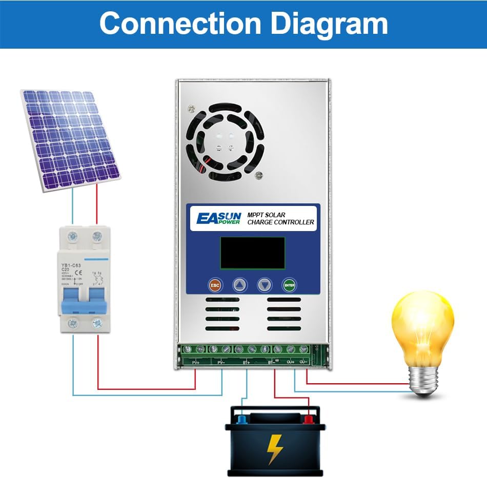
Figure 4.1: Standard connection diagram for the MPPT solar charge controller. Connect battery first, then PV, then load.
- Connect the Battery: Connect the positive and negative terminals of the battery to the corresponding battery terminals on the controller. Ensure correct polarity. The controller will automatically detect the battery voltage.
- Connect the Solar Panels (PV Array): Connect the positive and negative terminals of your solar panel array to the PV input terminals on the controller. Ensure the PV open circuit voltage does not exceed 180V.
- Connect the Load (Optional): If using the load output terminals, connect your DC load to the load terminals. Ensure the load current does not exceed the controller's rated load current.
Important Safety Note: Always disconnect solar panels and load before disconnecting the battery. Disconnect in reverse order of connection for safety.
4.3. Parallel Connection:
Multiple MPPT controllers can be connected in parallel to handle larger solar arrays and battery banks. This allows for system expansion and increased power capacity.

Figure 4.2: Example of parallel connection for multiple MPPT controllers in a larger solar power system.
5. Operating Instructions
The controller features an intuitive LCD display for monitoring system status and adjusting parameters. The display provides real-time data on battery voltage, charging current, PV input, and load status.
5.1. LCD Display and Button Functions:
The LCD screen allows you to navigate through various settings and view operational data. The buttons typically include ESC (Escape/Back), Up, Down, and ENTER (Confirm).

Figure 5.1: Flowchart illustrating the LCD display menu for parameter settings, including battery type, system voltage, and various charge voltages.
5.2. Parameter Settings:
The controller automatically adjusts for sealed lead-acid, vented gel batteries, etc. However, for lithium batteries, manual adjustment of parameters is required due to their unstable voltage characteristics.
- Battery Type (Set1): Select the appropriate battery type (e.g., SEL/GEL/FLD).
- System Voltage (Set2): Confirm or manually set the system voltage (Auto/12/24/36/48V).
- Charge Voltages (Set3-Set5): Adjust Equalization Charge Voltage (EQU), Boost Charge Voltage (BST), and Float Charge Voltage (FLD) as needed, especially for lithium batteries.
- Load Mode (Set9): Configure the load output mode if applicable.
- Refer to the LCD display flowchart (Figure 5.1) for navigation and specific parameter adjustment steps.
6. Maintenance
Regular maintenance ensures the longevity and optimal performance of your POWLAND MPPT Solar Controller.
- Cleanliness: Keep the controller clean and free from dust and debris. Use a dry cloth for cleaning.
- Connections: Periodically check all wiring connections for tightness and corrosion. Loose connections can lead to power loss or overheating.
- Ventilation: Ensure the cooling fan and ventilation openings are not obstructed. The fan operates automatically when the internal temperature exceeds 45℃ and turns off below 40℃.
- Environmental Conditions: Verify that the operating environment remains within the specified temperature range (-20℃ to 55℃).
7. Troubleshooting
This section provides solutions to common issues you might encounter with your solar charge controller. The multi-function LCD display is designed to help quickly identify system faults.
| Problem | Possible Cause | Solution |
|---|---|---|
| No display or power | Battery not connected or low voltage; reversed polarity; loose connection. | Check battery connections and voltage. Ensure correct polarity. Tighten all terminals. |
| Battery not charging | PV panels not connected; insufficient sunlight; PV voltage too low/high; controller fault. | Check PV connections. Ensure panels are receiving adequate sunlight. Verify PV voltage is within specifications (Max 180Voc). |
| Overcharging battery | Incorrect battery type setting; controller fault. | Verify battery type setting on LCD. If issue persists, contact support. |
| Load not working | Load disconnected; load overcurrent; battery low voltage cut-off. | Check load connections. Reduce load if overcurrent. Charge battery. |
| Controller overheating | Poor ventilation; excessive load/PV input. | Ensure proper airflow around the unit. Reduce load or check PV input. |
8. Warranty and Support
POWLAND is committed to providing high-quality products. For any technical support or warranty inquiries, please contact your retailer or the manufacturer directly.
Manufacturer: EASUNPOWER
Please have your product model number (ICharger-MPPT-6048) and purchase details ready when contacting support.
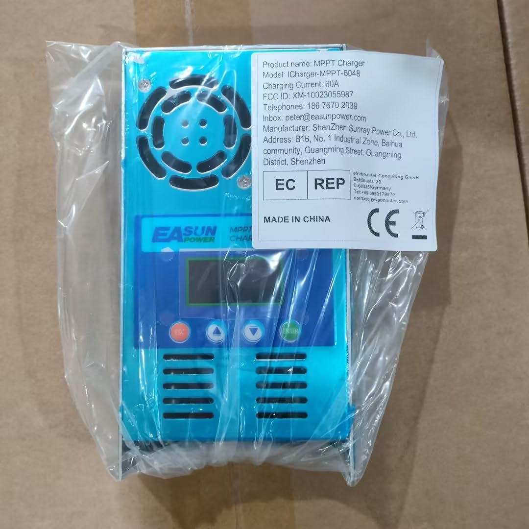
Figure 8.1: Product packaging showing the model number and manufacturer details.
Ask a question about this manual
Ask about setup, troubleshooting, compatibility, parts, safety, or missing instructions. Manuals+ will review the question and use this page’s manual context to help answer it.