1. Introduction
This manual provides detailed instructions for the installation, operation, and maintenance of the Jieotwice FH8-6CRNB Automatic Control Counter Meter. Please read this manual thoroughly before using the device to ensure correct operation and to prevent damage.
The FH8-6CRNB is an automatic control counter/meter counter designed for various industrial applications, including machinery, electronics, food processing, packaging, leather, and textile industries. It features a 6-digit LED display and relay output for control functions.
2. Product Overview
The Jieotwice FH8-6CRNB is a versatile digital counter capable of accumulating counts, recording data, and providing automatic control alarms and cycle alarms. It accepts NPN/PNP pulse signals for input and provides a relay output for control.
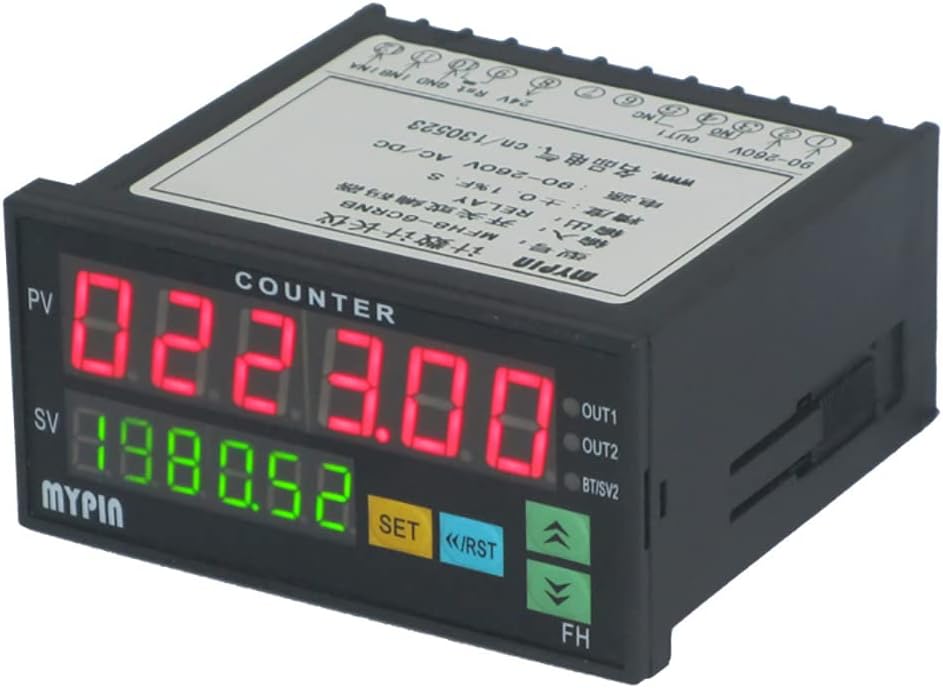
Figure 1: Front view of the FH8-6CRNB counter meter. It features a red 6-digit LED display for the Process Value (PV) and a green 6-digit LED display for the Set Value (SV). Control buttons include SET, Reset (RST), Up arrow, and Down arrow. Output indicators (OUT1, OUT2) are also visible.
3. Specifications
| Parameter | Value |
|---|---|
| Product Model | FH8-6CRNB |
| Dimensions | 48mm x 96mm x 80mm |
| Hole Size | 45mm x 91mm |
| Net Weight | 0.2 kg |
| Input Signal | NPN/PNP pulse signal (5V ≤ H ≤ 30V, 0V ≤ L ≤ 2V), rising edge trigger |
| Output | A RELAY relay output |
| Counting Speed | ≤ 5000 CPS |
| Auxiliary Power Supply | 24V DC |
| Power Supply | 90-265V AC/DC |
| Power Consumption | < 3W |
| Display Count Range | -199999 to 999999 |
| Accuracy | ± 0.1% F.S |
4. Package Contents
The package includes the following items:
- 1 x FH series automatic control Counter counter/meter counter (FH8-6CRNB)
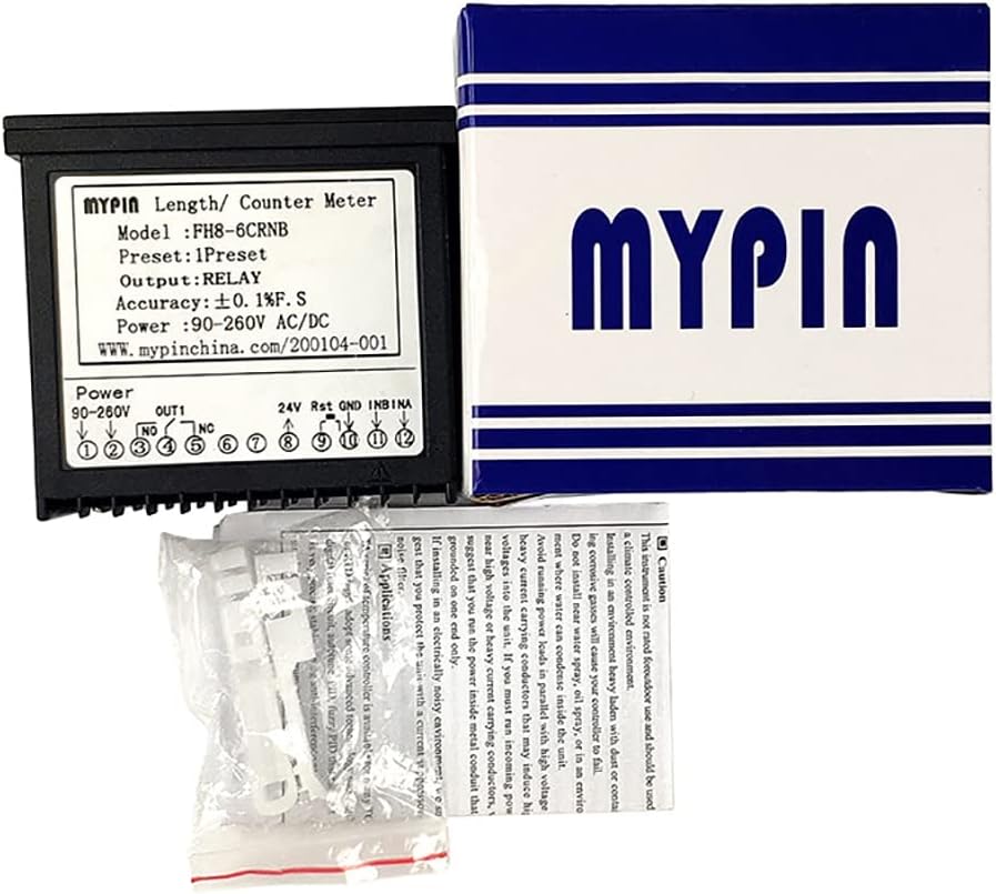
Figure 2: Contents of the product package, showing the FH8-6CRNB counter meter, its retail box, and small plastic accessories, likely mounting clips or terminal covers.
5. Safety Information and Precautions
WARNING:
- This product is not rated for outdoor use and should be used in a climate-controlled environment.
- Installing in an environment heavy with dust or containing corrosive gases will cause your counter to fail.
- Do not install near water spray, oil spray, or an environment where condensation is likely to occur.
- Do not route power leads in parallel with high voltage heavy current carrying conductors that may induce high voltages into the unit. If you must run them in parallel, it is suggested that you run the power inside metal conduit that is grounded on one end only.
- To prevent electrical noise, avoid placing the counter in an environment with strong electromagnetic interference.
- Ensure proper grounding to protect against electrical shock.
Always disconnect power before performing any installation or maintenance procedures.
6. Installation and Wiring
6.1. Mounting
The counter is designed for panel mounting. The required panel cut-out dimensions are 45mm x 91mm. Ensure sufficient space behind the panel for wiring and ventilation.
6.2. Wiring Diagram
Refer to the wiring diagram located on the top/back label of the device for correct connections. Ensure all connections are secure and comply with local electrical codes.
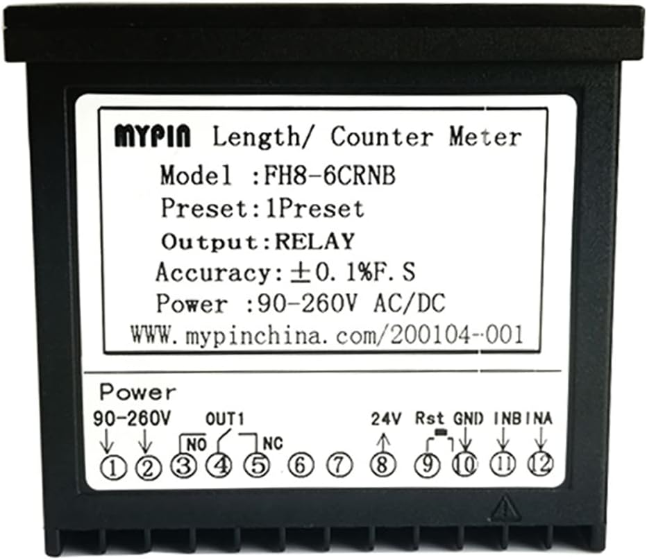
Figure 3: Top view of the FH8-6CRNB counter, displaying the model number, preset information, output type (RELAY), accuracy, and power requirements. A detailed wiring diagram is also visible, indicating terminals for power (90-260V), relay output (OUT1: NO, NC), 24V auxiliary power, Reset (Rst), Ground (GND), and input signals (INB, INA).

Figure 4: Bottom view of the FH8-6CRNB counter, showing the screw terminal block with numbered terminals (1-12 and 13-24). These terminals correspond to the wiring diagram for power, input, and output connections.
6.3. Power Supply Connection
Connect the main power supply (90-265V AC/DC) to the designated power terminals as indicated in the wiring diagram (typically terminals 1 and 2). Ensure the power source matches the specified voltage range.
6.4. Input Signal Connection
Connect your NPN/PNP pulse signal source to the INA and INB terminals. The device triggers on the rising edge of the pulse. Ensure the signal voltage levels are within the specified range (5V ≤ H ≤ 30V, 0V ≤ L ≤ 2V).
6.5. Relay Output Connection
The counter provides a relay output (OUT1) with Normally Open (NO) and Normally Closed (NC) contacts. Connect your control circuit to these terminals as required by your application. The relay activates based on the programmed set value and alarm conditions.
6.6. Auxiliary Power and Reset
An auxiliary 24V DC power supply can be connected to the designated terminals if needed for external sensors or components. The Reset (Rst) terminal allows for external resetting of the counter.
7. Operation
7.1. Display Overview
- PV (Process Value): The upper red LED display shows the current count or measured value.
- SV (Set Value): The lower green LED display shows the programmed set point or target value.
7.2. Button Functions
- SET Button: Used to enter programming mode and confirm settings.
- <</RST Button: Used to shift digits during setting or to manually reset the counter.
- Up Arrow (▲) Button: Used to increment values during setting.
- Down Arrow (▼) Button: Used to decrement values during setting.
7.3. Main Functions
The FH8-6CRNB supports the following primary functions:
- Accumulative Counting: Continuously counts input pulses.
- Record Function: Stores count data.
- Automatic Control Alarm: Triggers the relay output when the PV reaches the SV.
- Automatic Cycle Alarm: Configurable for repetitive alarm cycles.
Detailed programming instructions for setting the SV, alarm modes, and other parameters are typically found in the full product manual. Refer to the manufacturer's website or contact support for advanced configuration.
8. Maintenance
The Jieotwice FH8-6CRNB counter meter requires minimal maintenance. Follow these guidelines to ensure longevity:
- Keep the device clean and free from dust and debris. Use a soft, dry cloth for cleaning.
- Ensure the operating environment remains within specified temperature and humidity ranges.
- Regularly check wiring connections for tightness and signs of wear.
- Avoid exposing the device to strong vibrations or impacts.
9. Troubleshooting
If you encounter issues with your FH8-6CRNB counter, consider the following common troubleshooting steps:
- No Display: Check the power supply connection (90-265V AC/DC). Ensure power is applied and within the specified range.
- Incorrect Counting: Verify the input signal connections (INA, INB) and ensure the signal type (NPN/PNP) and voltage levels are correct. Check for electrical noise interference.
- Relay Not Activating: Confirm the set value (SV) is correctly programmed. Check the relay output wiring (NO, NC contacts) and the external control circuit.
- Counter Resets Unexpectedly: Check the Reset (Rst) terminal for unintended signals or short circuits. Ensure stable power supply.
For persistent issues or advanced diagnostics, please contact Jieotwice customer support.
10. Warranty and Support
For information regarding warranty coverage, technical support, or service, please refer to the documentation provided with your purchase or visit the official Jieotwice website. Keep your purchase receipt as proof of purchase.