1. Introduction
The RadioMaster ER6 ELRS PWM Receiver is designed for fixed-wing RC aircraft, leveraging the advanced ExpressLRS system for high performance and reliability. This 2.4GHz, 6-channel receiver offers flexible configuration, fast response, and extended range capabilities.
Key features include:
- ExpressLRS System: Utilizes the ExpressLRS protocol for robust and long-range control.
- 6 PWM Channels: Capable of driving up to six servos, ideal for fixed-wing applications.
- Telemetry: Built-in receiver voltage telemetry and automatic flight battery voltage detection.
- Advanced Configuration: Supports Wi-Fi updates and WEBUI configuration for easy management.
- CRSF Interface: Features a 4-wire CRSF interface for future expansion with additional telemetry sensors.
- Durable Design: One-piece molded shell for high structural strength.
- High-Quality Components: Includes a 20 cm dual antenna and 2.54 mm gold-plated connectors.

Image 1.1: The RadioMaster ER6 ELRS PWM Receiver, designed for fixed-wing aircraft.

Image 1.2: Diagram illustrating key features of the ExpressLRS system, including high performance, reliability, and range.
2. Setup
2.1 Package Contents
Verify that your package contains the following items:
- RadioMaster ER6 ELRS PWM Receiver
- 20 cm Dual Antenna
- Voltage Telemetry Wire
- CRSF Wire
- ELRS-RX-SBUS Wire
- User Card (Quick Start Guide)
2.2 Physical Connections
Connect the receiver to your fixed-wing aircraft's flight controller and servos as follows:
- Power Input: The receiver operates on DC 4.5-8.4V. Connect your power source to the designated BATT pins.
- Servo Connections: Connect your servos to channels CH1 through CH6. Ensure correct polarity (Signal, Positive, Negative).
- Antenna Installation: Connect the dual antennas to the receiver. Position them at a 90-degree angle to each other for optimal signal reception.
- Telemetry Connections:
- Use the provided Voltage Telemetry Wire to connect for flight battery voltage monitoring.
- Utilize the CRSF Wire for connecting to a flight controller or for future telemetry sensor expansion via the 4-pin CRSF interface.
- The ELRS-RX-SBUS wire can be used for SBUS output if required by your flight controller.

Image 2.1: Front view of the ER6 receiver showing the 6 PWM servo output channels (CH1-CH6) and battery input (BATT).
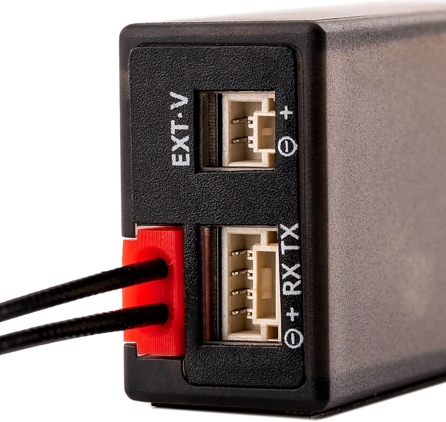
Image 2.2: Close-up of the side ports, including EXT-V for external voltage telemetry and RX TX for CRSF communication.
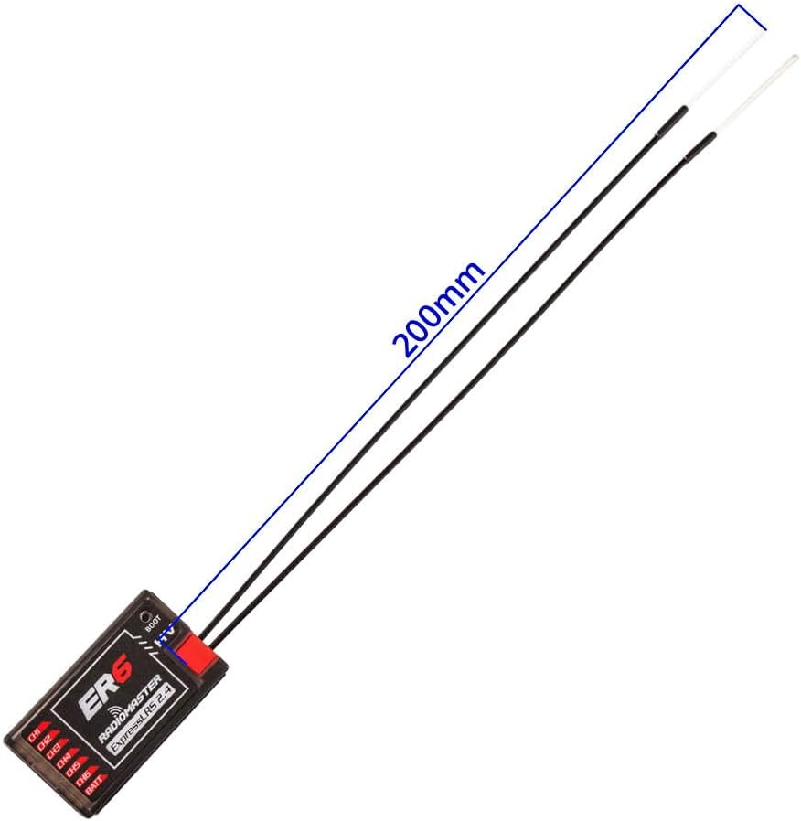
Image 2.3: The ER6 receiver with its 200mm dual antennas connected, illustrating proper antenna length.

Image 2.4: The ER6 receiver demonstrating connections to multiple servos, highlighting its 6 PWM channel support.
2.3 Binding Procedure
To establish communication between your transmitter and the ER6 receiver, follow the standard ExpressLRS binding procedure:
- Ensure your transmitter is running ExpressLRS firmware and is configured for 2.4GHz.
- Power on the ER6 receiver three times, cycling power off and on quickly between each power-up. After the third power cycle, the receiver's LED should flash rapidly, indicating it is in binding mode.
- On your ExpressLRS transmitter module, initiate the binding process. Refer to your transmitter's manual for specific instructions on how to enter binding mode.
- Once bound, the receiver's LED will turn solid, indicating a successful connection.
- If binding fails, ensure both transmitter and receiver are running compatible ExpressLRS firmware versions.
2.4 Initial Configuration (Wi-Fi & WEBUI)
The ER6 receiver supports Wi-Fi updates and WEBUI configuration for advanced settings and firmware management.
- Power on the receiver.
- Connect to the receiver's Wi-Fi hotspot using a computer or mobile device. The network name (SSID) will typically be "ExpressLRS RX" followed by a unique identifier.
- Open a web browser and navigate to http://10.0.0.1.
- The ExpressLRS WEBUI will load, allowing you to configure settings, update firmware, and monitor receiver status.
3. Operating Instructions
3.1 Basic Operation
Once successfully bound and configured, the ER6 receiver will output PWM signals to the connected servos based on the commands received from your ExpressLRS transmitter.
- Power On: Ensure the receiver is powered within its specified voltage range (DC 4.5-8.4V).
- Signal Reception: The receiver's LED will indicate signal status (solid for connected, flashing for binding/no signal).
- Servo Control: Channels CH1-CH6 will provide PWM output for controlling flight surfaces and other functions.
3.2 Telemetry Functions
The ER6 receiver provides essential telemetry data back to your transmitter:
- Receiver Voltage: Monitors the voltage supplied to the receiver.
- Flight Battery Voltage: Automatically detects and transmits the flight battery voltage when connected via the telemetry wire.
- CRSF Telemetry: The 4-wire CRSF interface allows for advanced telemetry data from compatible flight controllers or external sensors.

Image 3.1: Close-up of the 4-pin CRSF input, designed for future optional telemetry sensors.
4. Maintenance
4.1 Firmware Updates
Regularly updating the receiver's firmware is recommended to ensure optimal performance, access new features, and maintain compatibility with the latest ExpressLRS versions. Firmware updates can be performed via the Wi-Fi WEBUI as described in Section 2.4.
4.2 General Care
- Keep the receiver clean and free from dust, dirt, and moisture.
- Avoid exposing the receiver to extreme temperatures or direct sunlight for prolonged periods.
- Ensure all connections are secure before operation.
- Inspect antennas for any damage before each flight.
5. Troubleshooting
If you encounter issues with your ER6 receiver, consider the following troubleshooting steps:
- No Signal / Binding Issues:
- Verify that both the transmitter and receiver are powered on and within range.
- Confirm that the transmitter module is correctly configured for ExpressLRS 2.4GHz.
- Ensure the receiver's LED is flashing rapidly when attempting to bind. If not, re-perform the power cycle binding procedure.
- Check for firmware compatibility between your transmitter and receiver. Update firmware if necessary.
- Inspect antennas for damage or improper connection.
- Intermittent Signal Loss:
- Check antenna placement and orientation on the aircraft. Avoid placing antennas near carbon fiber or large metal objects that can block signals.
- Ensure there are no sources of interference (e.g., noisy ESCs, video transmitters) too close to the receiver or antennas.
- Verify power supply to the receiver is stable and within the specified voltage range.
- Incorrect Servo Response:
- Confirm servo connections to the correct PWM channels (CH1-CH6) and correct polarity.
- Check your transmitter's channel mapping and mixer settings.
- Ensure the flight controller (if used) is correctly configured to interpret receiver inputs.
- Telemetry Not Working:
- Verify the voltage telemetry wire is correctly connected to the flight battery.
- Ensure the CRSF wire is properly connected if using external telemetry sensors or a flight controller.
- Check your transmitter's telemetry settings to ensure it is configured to display incoming data.
6. Specifications
| Brand | SPEEDY BEE |
| Model Name | ER6 |
| Wireless Type | 2.4 GHz Radio Frequency (ExpressLRS) |
| Channels | 6 PWM Output |
| Input Voltage | DC 4.5-8.4V |
| Telemetry | Receiver Voltage, Flight Battery Voltage, CRSF Interface |
| Connectivity | Wi-Fi (for updates and configuration) |
| Antenna | 20 cm Dual Antenna |
| Dimensions (LxWxH) | 1.46 x 0.75 x 0.51 inches (37 x 19 x 13 mm approx.) |
| Item Weight | 2.92 ounces (82.78 grams approx.) |
| Manufacturer | RadioMaster |
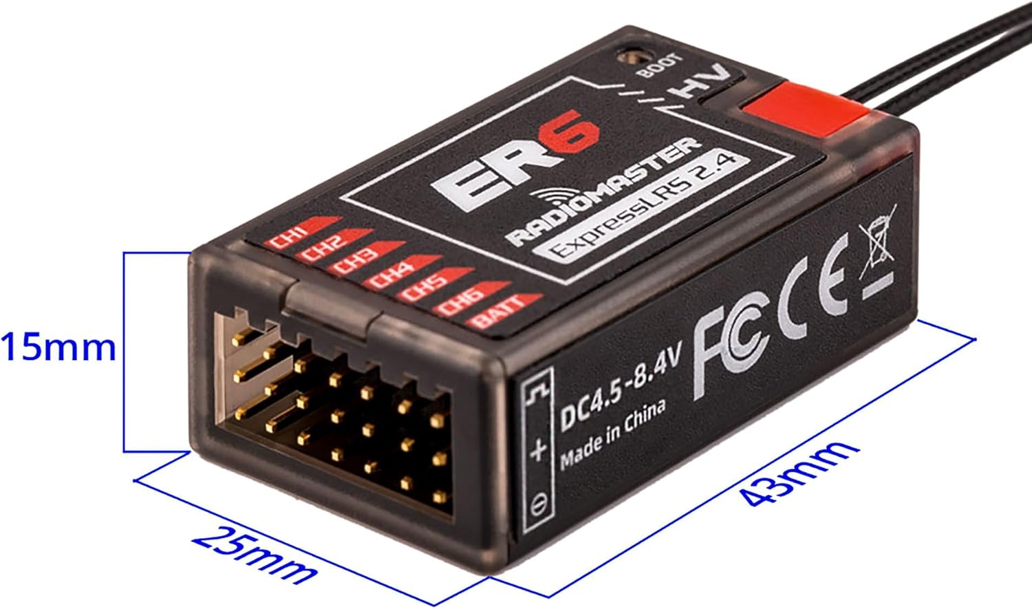
Image 6.1: Diagram showing the physical dimensions of the ER6 receiver (43mm length, 25mm width, 15mm height).

Image 6.2: Bottom view of the ER6 receiver, indicating the DC 4.5-8.4V power input range and regulatory markings.

Image 6.3: Internal view of the ER6 receiver's power supply, engineered for consistent MCU voltage and stability.

Image 6.4: Highlighting the quality 2.54mm gold-plated connectors and the exquisite, durable case design of the ER6 receiver.
7. Warranty and Support
Specific warranty details and direct support contact information are not provided within this manual. For warranty claims, technical support, or service inquiries, please refer to the official SPEEDY BEE website or contact your retailer.