
Introduction
This instruction manual provides comprehensive guidance for the BearHoHo 4-Button LED Escape Room Prop. This device is designed to enhance escape room experiences by requiring players to press metal buttons in a specific color sequence to trigger an electromagnetic lock. The prop features 7-color LED buttons and a customizable trigger mechanism. Please read this manual thoroughly before installation and operation to ensure proper functionality and safety.
Package Contents
Verify that all items listed below are included in your package:
- 1 x Controller (with Speaker)
- 4 x Metal Buttons (with 7 LED colors)
- 1 x 12V Power Adapter
- 1 x USB Cable
- 1 x User Manual
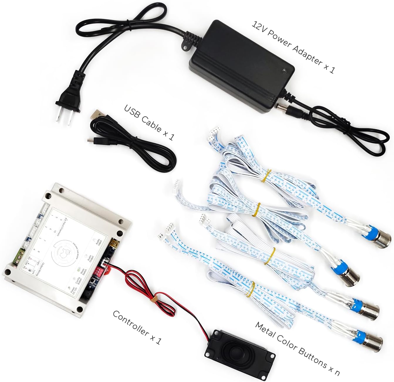
Figure 1: Package Contents. This image displays the controller, four metal buttons, 12V power adapter, USB cable, and speaker.
Product Features
- Each metal button features 7 distinct LED colors: red, yellow, blue, green, purple, white, and orange.
- Button color changes with each press, allowing for complex color-based puzzles.
- Designed to control a 12V electric magnetic lock for triggering escape room events.
- Offers three distinct reset modes for flexible game design.
- Supports user-customizable audio content (MP3 format, up to 16MB).
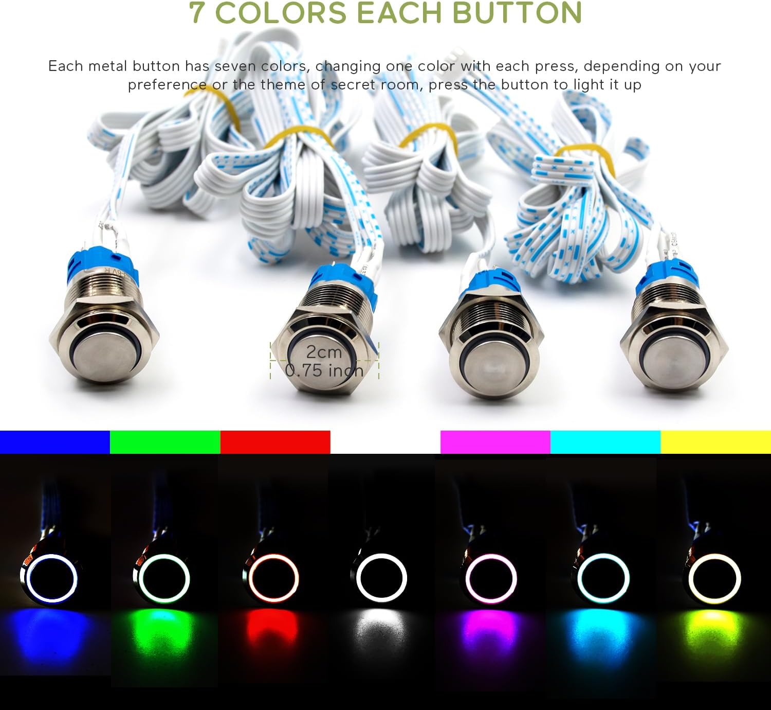
Figure 2: 7-Color LED Buttons. This image shows the metal buttons and their ability to display seven different LED colors.
Setup Instructions
Connecting the 12V Electromagnetic Lock (EM Lock)
The prop is designed to work with a 12V electromagnetic lock. Ensure your EM lock is rated for 12V to prevent damage or malfunction. EM locks are not included with this product and must be provided separately.
- Connect the red wire of your electromagnetic lock to the NC (Normally Closed) port on the controller.
- Connect the black wire of your electromagnetic lock to the COM (Common) port on the controller.

Figure 3: EM Lock Connection Diagram. This diagram shows how to correctly wire a 12V electromagnetic lock to the controller's NC and COM ports.
Controller Overview

Figure 4: Controller Component Diagram. This image provides a detailed view of the controller, highlighting its various ports and functions for setup and configuration.
Operation
Players interact with the prop by pressing the metal buttons. Each press cycles the button's LED through its 7 available colors. The objective is to achieve a specific color combination across all buttons. Once all buttons display the pre-configured colors, the prop will trigger, and the connected electromagnetic lock will open.
Configuration
Modifying the Color Settings (Trigger Password)
Follow these steps to customize the required color sequence for triggering the prop:
- Power Off: Disconnect the power adapter from the controller.
- Enter Settings Mode: Press and hold the Settings button (located next to the power port). While holding the button, reconnect the power adapter. Continue holding until you hear a voice prompt, then release the button.
- Set Colors: Listen for the voice prompt to end. Then, press each metal button multiple times until it displays the desired color for your new trigger sequence.
- Save Settings: Press the Settings button once more to save the newly configured colors. The controller will automatically reboot to apply the changes.
- Test: After reboot, test the prop with your new color sequence.
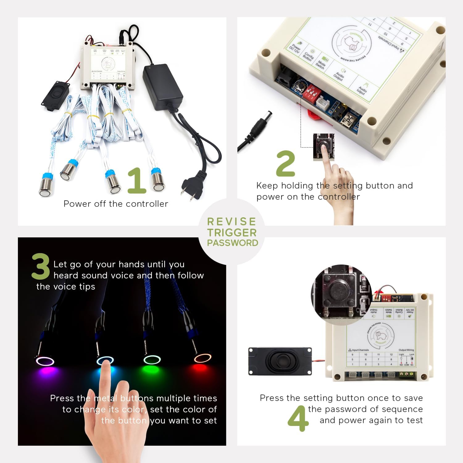
Figure 5: Color Setting Procedure. This image illustrates the steps to modify the required color sequence for the buttons.
Modifying the Reset Mode
The reset mode can be adjusted using the settings switch (DIP switch) located next to the power port on the controller.
- Automatically Reset Mode: Set DIP switch #3 to the UP position. The prop will automatically reset after 1 minute following a successful trigger.
- Real-Time Reset Mode: Set DIP switch #3 to the DOWN position. The prop will reset immediately upon any button press after a successful trigger.
Modifying Voice Files
You can customize the audio prompts played by the controller:
- Connect to PC: Insert the USB cable into the controller and connect the other end to your PC.
- Backup Files: Open the removable disk that appears on your PC. It is highly recommended to back up all original files from the controller to your computer.
- Replace Audio: Replace the original audio file(s) with your preferred sound file(s). Ensure the new files have the exact same path and filename as the originals. The audio file format must be MP3. The total size of audio files should not exceed 16MB.
- Formatting (if necessary): If you need to format the removable disk, format it to FAT format only. Do NOT format it to FAT32, exFAT, or NTFS.
Resetting the Prop
There are three methods to reset the prop after it has been triggered:
- Automatic Reset: If configured, the prop will automatically reset 1 minute after a successful trigger.
- Real-Time Reset: If configured, pressing any button again after a successful trigger will reset the prop.
- Manual Reset: Power cycling the controller (disconnecting and reconnecting the 12V power adapter) will reset the prop.
Specifications
| Feature | Detail |
|---|---|
| Manufacturer | Bearhoho |
| Model Number | DC-ERP015 |
| Product Dimensions | 3.94 x 3.94 x 1.57 inches (Controller) |
| Number of Buttons | 4 Buttons |
| Audio Feature | No Audio (for this variant) |
| Included Components | LED Color Metal Buttons, Controller, 12V Power Adapter, USB Cable, Speaker |
| Batteries Required? | No |
| ASIN | B0C9WSRMP2 |
| Date First Available | July 1, 2023 |
Troubleshooting
If you encounter issues with your BearHoHo 4-Button LED Escape Room Prop, consider the following:
- No Power: Ensure the 12V power adapter is securely connected to both the controller and a working power outlet.
- EM Lock Not Triggering: Verify that the EM lock is correctly wired to the NC and COM ports as described in the "Connecting the 12V EM Lock" section. Confirm the EM lock is a 12V model.
- Buttons Not Responding/Incorrect Colors: Check all button connections to the controller. If colors are incorrect, re-perform the "Modifying the Color Settings" procedure.
- Audio Issues: If you have customized audio, ensure the MP3 files are correctly named, in the right directory, and formatted as FAT (not FAT32, exFAT, or NTFS).
- Unexpected Reset Behavior: Verify the DIP switch setting for the reset mode is correctly configured according to your preference.
For persistent issues, please refer to the support information below.
Warranty and Support
This product is covered by a standard manufacturer's warranty. For specific warranty details, technical support, or assistance with any issues not covered in this manual, please contact BearHoHo customer service through the retailer's platform or the official BearHoHo website. Please have your model number (DC-ERP015) and purchase information ready when contacting support.