tingbowie DIY Electronic Soldering Practice Kit
tingbowie DIY Electronic Soldering Practice Kit User Manual
Model: Soldering Practice Kit
1. Introduction
This user manual provides instructions for assembling and operating the tingbowie DIY Electronic Soldering Practice Kit. This kit is designed for beginners to learn fundamental electronics concepts and develop soldering skills through a practical project. Upon completion, the circuit board will display a heart-shaped pattern of flashing LEDs.
2. Safety Information
- Always work in a well-ventilated area to avoid inhaling solder fumes.
- Use appropriate personal protective equipment, such as safety glasses, to protect your eyes from solder splashes or flying debris.
- Soldering irons become extremely hot. Avoid direct contact with the heating element and allow the iron to cool completely before storing.
- Keep flammable materials away from your soldering workstation.
- Ensure proper disposal of electronic waste and solder residues.
- This kit contains small components and is not suitable for children under 14 years old without adult supervision.
3. Package Contents
Please verify that all components listed below are present in your kit before beginning assembly. Refer to the image for visual identification of parts.

Image: Kit components
- 1x Printed Circuit Board (PCB)
- 18x LEDs (Light Emitting Diodes)
- 6x Resistors (various values, typically 10KΩ and 100Ω)
- 3x Capacitors (typically 10µF electrolytic)
- 3x Transistors (typically 9014 NPN)
- 1x Power Connector (e.g., 2-pin header for battery or USB cable)
4. Assembly Instructions
Follow these steps carefully to assemble your soldering practice kit. Component names are marked on the PCB for easy identification.
4.1 General Soldering Tips
- Ensure your soldering iron tip is clean and tinned.
- Heat both the component lead and the PCB pad simultaneously.
- Apply a small amount of solder to the heated joint, allowing it to flow smoothly.
- Remove the solder, then the iron, and allow the joint to cool without disturbance.
- Trim excess component leads after soldering.
4.2 Step-by-Step Assembly
- Resistors: Identify the resistors (R1, R2, R3, R4, R5, R6) by their color codes or markings. Insert them into their designated positions on the PCB and solder them in place. Trim the excess leads.
- Transistors: Locate the transistor positions (Q1, Q2, Q3). Ensure the flat side of each transistor matches the outline on the PCB. Insert and solder them.
- Capacitors: Identify the electrolytic capacitors (C1, C2, C3). These are polarized, meaning they have a positive and negative lead. The longer lead is typically positive (+), and the negative lead is usually marked with a stripe on the capacitor body. Match the polarity markings on the capacitor to the PCB (the PCB usually has a '+' sign or a shaded area for the negative side). Insert and solder them.
- LEDs: The LEDs are also polarized. The longer lead is the anode (+), and the shorter lead is the cathode (-). The PCB will have markings (often a flat edge on the circle or a '+' sign) to indicate the correct orientation. Carefully insert all 18 LEDs into their heart-shaped pattern and solder them.
- Power Connector: Solder the 2-pin power connector into its designated spot.

Image: Fully assembled circuit board
5. Circuit Diagram
For reference and deeper understanding, the circuit diagram for the tingbowie DIY Electronic Soldering Practice Kit is provided below. This diagram illustrates the connections between the various components.
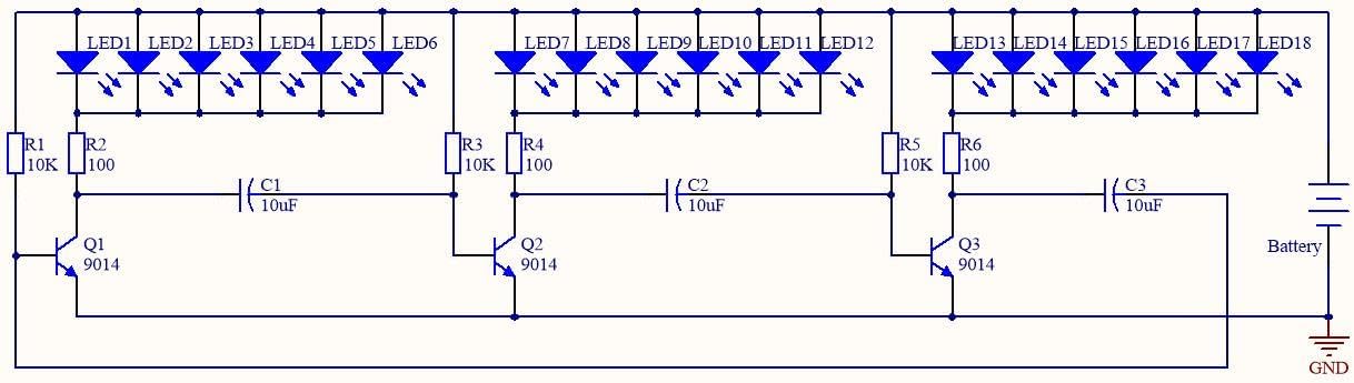
Image: Circuit Diagram
6. Operation
Once assembly is complete, connect a 3V DC power source to the power connector. This can typically be achieved using a 2x AA battery holder or a compatible USB power cable (not included). The LEDs will begin to flash in a continuous, dynamic heart-shaped pattern.

Image: Assembled kit in operation
6.1 Demonstration Video
Watch this video to see the completed tingbowie DIY Electronic Soldering Practice Kit in action, demonstrating the flashing LED effect.
Video: Effect of the finished product, showing the heart-shaped LED pattern flashing in various colors.
7. Troubleshooting
| Problem | Possible Cause | Solution |
|---|---|---|
| No LEDs light up. |
|
|
| Some LEDs do not light up. |
|
|
| LEDs are dim or flicker erratically. |
|
|
8. Specifications
- Product Dimensions: 2 x 2 x 0.6 inches
- Item Weight: 0.634 ounces
- Power Requirement: 3V DC (e.g., 2x AA batteries or compatible USB power)
- Manufacturer: Tingbowie
- Recommended Age: 14 years and up (due to soldering requirement)
9. Warranty and Support
This tingbowie DIY Electronic Soldering Practice Kit is designed for educational purposes. Due to the nature of DIY assembly, specific warranties may vary. For support regarding missing components or manufacturing defects, please contact the seller directly through your purchase platform. General troubleshooting tips are provided in this manual.
For additional resources and to explore more products, visit the tingbowie brand page on Amazon.
no relevant documents
Ask a question about this manual
Ask about setup, troubleshooting, compatibility, parts, safety, or missing instructions. Manuals+ will review the question and use this page’s manual context to help answer it.