1. Introduction
This manual provides detailed instructions for the safe and efficient operation of your Weytoll 4-in-1 MIG/MMA/MAG/TIG 160A Welding Machine. Please read this manual thoroughly before using the equipment to ensure proper setup, operation, and maintenance. Keep this manual for future reference.
2. Safety Instructions
WARNING: Welding can be dangerous. Always follow safety precautions to prevent injury or death.
- Eye Protection: Always wear a welding helmet with appropriate shade lenses to protect your eyes from arc rays.
- Body Protection: Wear flame-resistant clothing, gloves, and safety shoes to protect against sparks, heat, and electric shock.
- Ventilation: Ensure adequate ventilation to remove welding fumes and gases, which can be hazardous to your health.
- Fire Prevention: Keep a fire extinguisher nearby. Remove all flammable materials from the welding area.
- Electrical Safety: Ensure the welding machine is properly grounded. Do not operate in wet conditions. Inspect cables for damage before each use.
- Gas Cylinders: If using shielding gas, secure cylinders properly and handle them with care.
- Children and Bystanders: Keep children and unauthorized personnel away from the welding area.
3. Package Contents
Upon unpacking, verify that all items listed below are present and undamaged. If any items are missing or damaged, contact your supplier immediately.

Figure 3.1: Included accessories with the welding machine.
- 1 x Weytoll Welding Machine
- 1 x Electrode Holder
- 1 x 300A Welding Clamp (Ground Clamp)
- 1 x Roll of Welding Wire
- 1 x Welding Mask
- 1 x Steel Brush
- 1 x User Guide (This manual)
4. Product Features
The Weytoll 4-in-1 Welding Machine is designed for versatility and performance, offering multiple welding processes in a compact unit.

Figure 4.1: Overview of the welding machine's key features.
- Multifunctional Welding: Supports MIG (Gas & Gasless), MMA (Stick), MAG, and TIG welding processes.
- Digital Display: Large digital screen for clear display of welding current/voltage and convenient operation.
- Adjustable Parameters: Welding voltage and wire feed speed are adjustable to match material thickness.
- Multiple Protections: Equipped with over-temperature, over-current, and over-voltage protection for enhanced safety and reliability.
- IGBT Technology: Utilizes IGBT high-frequency inverter technology for stable electric arc, minimal splashing, and strong welding ability.
- Efficient Cooling: Features multiple exhaust holes and a built-in high-efficiency cooling fan to dissipate heat and extend machine lifespan.
5. Setup
5.1 Power Connection
- Ensure the power switch on the machine is in the "OFF" position.
- Connect the power cable to a suitable 220V power outlet. The machine requires a stable power supply.
5.2 Ground Clamp Connection
- Connect the ground clamp cable to the appropriate terminal on the front panel of the welding machine.
- Attach the ground clamp securely to the workpiece or welding table, ensuring good electrical contact.
5.3 Welding Wire Installation (MIG/MAG)
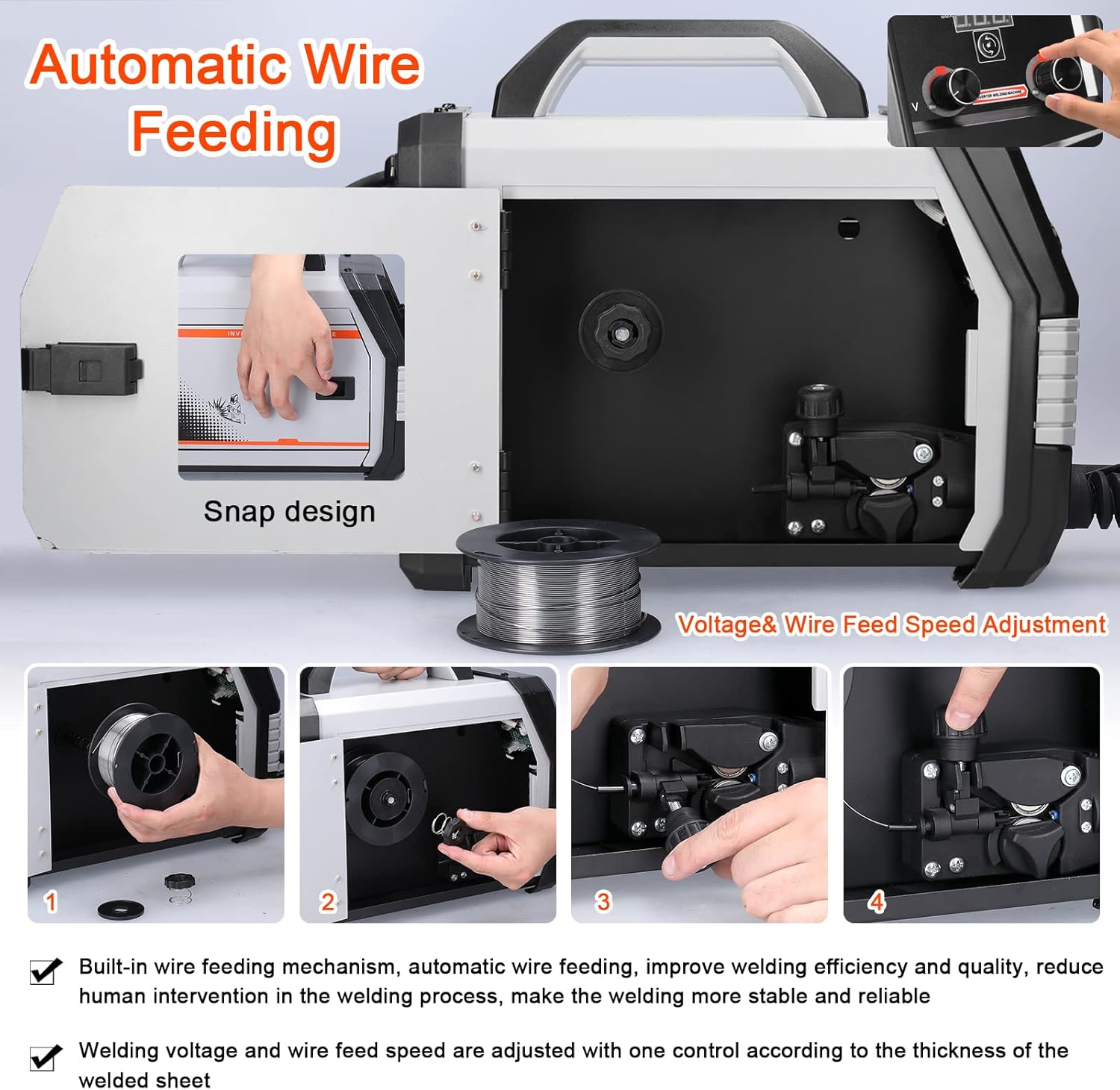
Figure 5.1: Automatic wire feeding mechanism and installation steps.
- Open the side cover of the machine to access the wire feeder compartment.
- Place the welding wire spool onto the spindle, ensuring it rotates freely.
- Thread the welding wire through the wire feeder mechanism, ensuring it passes through the drive rollers and into the liner.
- Adjust the tension of the drive rollers to prevent slipping or crushing of the wire.
- Close the side cover.
5.4 Gas Connection (MIG/MAG with Gas)
- Connect the gas hose from your shielding gas cylinder (e.g., CO2 for MIG solid wire) to the gas input port on the rear of the welding machine.
- Ensure all connections are tight to prevent gas leaks.
- Open the gas cylinder valve and adjust the flow rate using a regulator.
6. Operating Instructions
6.1 Powering On and Mode Selection

Figure 6.1: Front and rear panel controls.
- Turn the power switch to the "ON" position. The digital display will illuminate.
- Use the mode selection button (often labeled "MMA-TIG one piece switching" or similar) to choose your desired welding process: MIG, MMA, MAG, or TIG.
6.2 Parameter Adjustment
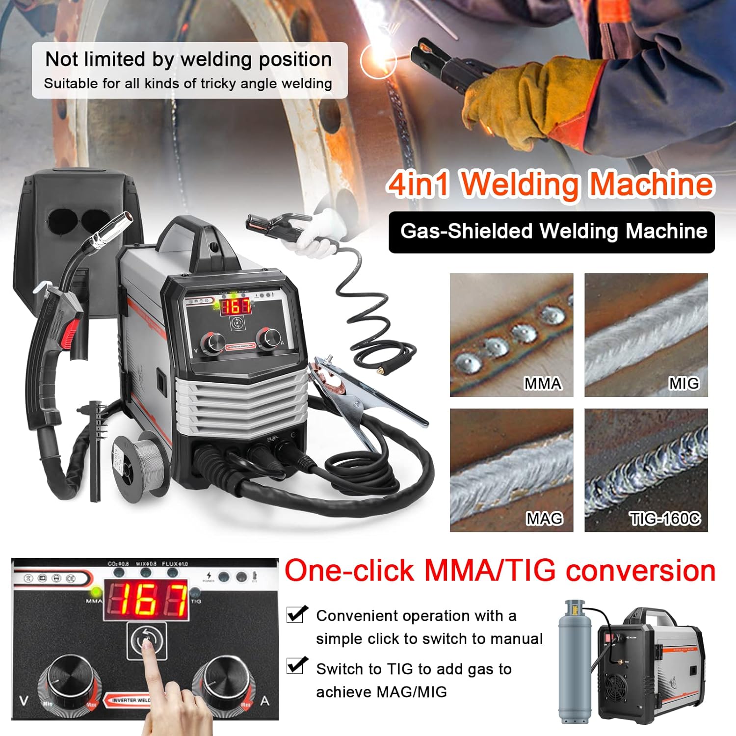
Figure 6.2: One-click mode conversion and weld examples.
- Current/Voltage: Use the control knobs on the front panel to adjust the welding current (A) and voltage (V) according to the material thickness and welding process. The digital display will show the current settings.
- Wire Feed Speed (MIG/MAG): Adjust the wire feed speed knob. This is often linked to voltage for optimal MIG/MAG performance.
6.3 Welding Process Specifics
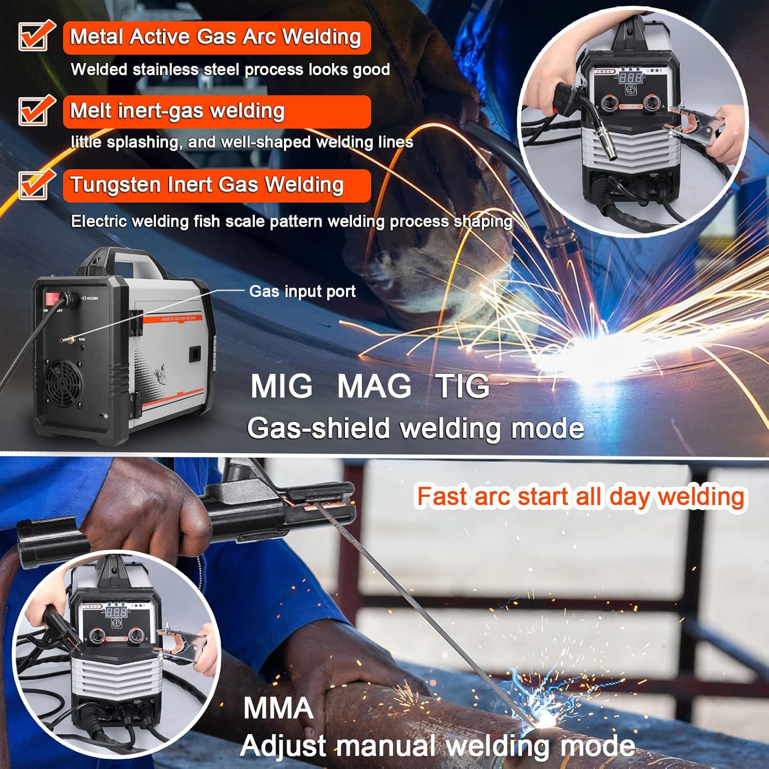
Figure 6.3: MIG/MAG/TIG and MMA welding in action.
6.3.1 MIG/MAG Welding (Gas-Shielded)
- Ensure gas cylinder is connected and gas flow is set.
- Use solid wire (e.g., 0.8mm for CO2 gas).
- Press the trigger on the MIG torch to initiate the arc and wire feed.
6.3.2 Gasless MIG Welding (Flux-Cored)
- No shielding gas required. Use flux-cored wire (e.g., 0.8mm - 1.0mm).
- Ensure polarity is set correctly for flux-cored wire (refer to wire manufacturer's instructions).
- Press the trigger on the MIG torch to initiate the arc and wire feed.
6.3.3 MMA (Stick) Welding
- Connect the electrode holder cable to the positive (+) terminal and the ground clamp to the negative (-) terminal (or vice-versa, depending on electrode type).
- Insert the electrode into the holder.
- Strike the arc by lightly touching and quickly lifting the electrode from the workpiece.
- Recommended electrode thickness: 1.6mm - 3.2mm.
6.3.4 TIG Welding
- Connect the TIG torch (not included in standard package) and gas supply (Argon).
- Ensure the tungsten electrode is properly ground.
- Initiate the arc (lift arc or high-frequency start, depending on machine features).
6.4 Welding Current Setting Reference
Refer to the table below for recommended welding current and voltage settings based on electrode diameter for MMA welding.

Figure 6.4: Reference table for welding current settings.
| Electrode dia. (mm) | Recommended welding current (A) | Recommended welding voltage (V) |
|---|---|---|
| 1.0 | 20~60 | 20.8~22.4 |
| 1.6 | 44~84 | 21.76~23.36 |
| 2.0 | 60~100 | 22.4~24.0 |
| 2.5 | 80~120 | 23.2~24.8 |
| 3.2 | 108~148 | 23.32~24.92 |
| 4.0 | 140~180 | 24.6~27.2 |
| 5.0 | 180~220 | 27.2~28.8 |
7. Maintenance
Regular maintenance ensures the longevity and safe operation of your welding machine.
- Cleaning: Regularly clean the machine's exterior with a dry cloth. Use compressed air to blow out dust from inside the machine, especially the cooling vents, at least once a month or more frequently in dusty environments. Ensure the machine is unplugged before cleaning.
- Cable Inspection: Inspect all welding cables, power cords, and gas hoses for cuts, abrasions, or loose connections before each use. Replace damaged components immediately.
- Wire Feeder: Clean the wire feeder rollers and guide tubes regularly to prevent wire feeding issues. Check for wear on the drive rollers.
- Torch/Electrode Holder: Clean the MIG torch nozzle and contact tip. Replace worn contact tips. Ensure the MMA electrode holder jaws are clean and grip electrodes securely.
- Storage: Store the welding machine in a clean, dry environment when not in use.
8. Troubleshooting
This section addresses common issues you might encounter. For problems not listed here, contact customer support.
| Problem | Possible Cause | Solution |
|---|---|---|
| Machine does not power on | No power supply; Power switch off; Faulty power cable/plug | Check power outlet; Ensure switch is ON; Inspect and replace cable if damaged. |
| No welding arc (MMA) | Poor ground connection; Incorrect current setting; Wet electrode; Faulty electrode holder | Ensure good ground contact; Adjust current; Use dry electrodes; Check electrode holder. |
| Wire not feeding (MIG/MAG) | Wire spool tangled; Drive rollers loose/worn; Contact tip clogged; Liner blocked | Untangle wire; Adjust/replace rollers; Clean/replace contact tip; Clean/replace liner. |
| Poor weld quality | Incorrect settings (current/voltage/wire speed); Improper technique; Contaminated workpiece; Insufficient gas flow (MIG/MAG) | Adjust settings; Practice technique; Clean workpiece; Check gas supply and flow rate. |
| Overheat protection activated | Exceeded duty cycle; Insufficient ventilation; Blocked cooling vents | Allow machine to cool down; Ensure proper ventilation; Clean cooling vents. |
9. Specifications
Technical specifications for the Weytoll 4-in-1 Welding Machine.
| Parameter | Value |
|---|---|
| Model | Schweißgerät 4in1 |
| Input Voltage | 220V |
| Output Current (A) | 20A-300A |
| Power Capacity (KVA) | 7.4 |
| Frequency (HZ) | 50/60 |
| Output Voltage (V) | 16.5-24 |
| Rated Duty Cycle (%) | 60 |
| Power Factor | 0.85 |
| Efficiency (%) | 85 |
| Wire Feeding Style | Internal |
| Wire Feed Speed (m/min) | 3.6-12 |
| Post-Flux Time (S) | 0.5±1 |
| Insulation Degree | F |
| Housing Protection Index | IP21 |
| Max Wire Spool Size | Φ200 |
| Ambient Temperature | -10 ℃ to 40 ℃ |
| Altitude | ≤ 1000 meters |
| Relative Humidity (40°C) | ≤ 50% |
| Relative Humidity (20°C) | ≤ 90% |
| Item Dimensions | 375 x 245 x 160 mm |
| Item Weight | 6740 g |
| Package Dimensions | 470 x 225 x 400 mm |
| Package Weight | 7000 g |
10. Warranty and Support
For warranty information or technical support, please refer to the documentation provided with your purchase or contact the retailer/manufacturer directly. Keep your proof of purchase for warranty claims.
Manufacturer: Weytoll


