1. Introduction
The RD RK6006/RK6006-BT is a high-performance, adjustable DC-DC step-down voltage bench power supply designed for various electronic applications, testing, and development. It offers precise control over output voltage and current, featuring a 4-digit display for accurate readings. The RK6006-BT model includes Bluetooth communication capabilities for enhanced control via PC software and mobile applications.
This manual provides essential information for the safe and efficient operation of your RK6006/RK6006-BT power supply. Please read it thoroughly before use.
2. Safety Instructions
- Always ensure the input voltage is within the specified range (12-68.00V) to prevent damage to the device.
- Do not operate the device in wet or damp conditions. Keep it away from liquids.
- Ensure proper ventilation to prevent overheating. The cooling fan operates automatically based on internal temperature and output current.
- Avoid short-circuiting the output terminals.
- Only use the specified 10A fuse. Refer to the maintenance section for fuse replacement.
- Do not attempt to disassemble or modify the device beyond what is described in this manual. Unauthorized modifications can void the warranty and pose safety risks.
- Connect the device to a suitable AC-DC power source (not included) before operation.
3. Package Contents
Verify that all items listed below are present in your package:
- RD RK6006/RK6006-BT Power Supply Unit
- 10A Fuse (spare)
- External Temperature Sensor (included with RK6006-BT model only)
- Bluetooth Board (pre-installed or included for RK6006-BT model only)
- User Manual (this document)

Figure 3.1: RK6006/RK6006-BT Power Supply and its components. This image illustrates the main unit, the 10A fuse, the packing box, the Bluetooth board (for RK6006-BT), and the external temperature sensor (for RK6006-BT).
4. Product Overview
4.1 Front Panel
Figure 4.1: Front panel display and controls. The display shows voltage, current, power, and other parameters. Controls include V-SET, I-SET, OK buttons, a rotary encoder, and an ON/OFF switch.
- Display: 1.54 inch 240*240 color HD display showing output voltage, current, power, and other operational data.
- V-SET Button: Used to enter voltage setting mode.
- I-SET Button: Used to enter current setting mode.
- OK Button: Confirms selections or exits menus.
- Rotary Encoder: Adjusts values and navigates menus.
- ON/OFF Switch: Toggles the output power.
4.2 Rear Connections and Internal Components

Figure 4.2: Internal connections. This image highlights the input positive/negative terminals, output positive/negative terminals, 10A fuse, backup fuse socket, external fan socket, communication socket, and temperature sensor socket. The Bluetooth board installation area is also shown.
- Input Positive/Negative: Terminals for connecting the external DC input power source.
- Output Positive/Negative: Terminals for connecting the load.
- 10A Fuse: Main protective fuse.
- Backup Fuse Socket: Provides a spare fuse for quick replacement.
- External Fan Socket: For connecting an optional external cooling fan (supports 5V 200mA max).
- Communication Socket: For USB communication with a PC.
- Temperature Sensor Socket: For connecting the external temperature sensor.
- Bluetooth Board Installation: Slot for the Bluetooth module (RK6006-BT only).
5. Specifications

Figure 5.1: Detailed technical parameters of the RK6006/RK6006-BT.
| Parameter | Value |
|---|---|
| Model | RK6006 / RK6006-BT |
| Input Voltage Range | 12-68.00V |
| Output Voltage Range | 0-60.00V |
| Output Current Range | 0-6.000A |
| Output Power Range | 0-360W |
| Input Voltage Measurement Resolution | 0.01V |
| Output Voltage Setting/Measurement Resolution | 0.01V |
| Output Current Setting/Measurement Resolution | 0.001A |
| Input Voltage Measurement Accuracy | ±(1%+5 digits) |
| Output Voltage Accuracy (Setting vs. Measurement) | ±(0.3%+3 digits) |
| Output Current Accuracy (Setting vs. Measurement) | ±(0.5%+5 digits) |
| Output Ripple Typical | 100mV VPP (measured at X1 range, AC coupling, 20MHz bandwidth with 0.1uF parallel capacitor at output) |
| Working Temperature Range | -10℃~40℃ |
| External Sensor Temperature Detection Range | -10℃~100℃ / 0℉~200℉ |
| External Sensor Temperature Detection Accuracy | ±3℃ / ±6℉ |
| Constant Voltage Mode Response Time | 2ms (0.1A-5A Load) |
| Constant Voltage Mode Load Regulation | ±(0.1%+2 digits) |
| Constant Current Mode Load Regulation | ±(0.1%+3 digits) |
| Capacity Measurement Range | 0-9999.99Ah |
| Energy Measurement Range | 0-9999.99Wh |
| Capacity and Energy Statistical Error | ±2% |
| Buck Working Mode | (Input Voltage ÷ 1.1) - 1V (e.g., 24V input, max output 20.8V) |
| Over Temperature Protection | System temperature > 80℃ |
| Screen Brightness Setting | 0-5 (6 levels in total) |
| Cooling Fan Start Condition | Output current > 4A or System temperature > 45℃ |
| Cooling Fan Shut Down Condition | Output current < 3.9A and System temperature < 45℃ |
| Weight (with package) | Approx. 0.15kg |
| Product Dimension | 79*43*54mm |
| USB Communication Support | Yes |
| Bluetooth Communication Support | Only RK6006-BT supports |
5.2 Product Dimensions

Figure 5.2: Physical dimensions of the RK6006/RK6006-BT unit, including recommended opening size for panel mounting.
6. Setup
6.1 Connecting Input Power
The RK6006/RK6006-BT requires an external AC-DC power source (not included) with an output voltage between 12V and 68V. Connect the positive (+) terminal of your AC-DC power source to the Input Positive terminal and the negative (-) terminal to the Input Negative terminal on the rear of the RK6006/RK6006-BT unit. Ensure connections are secure.
6.2 Connecting Output Load
Connect your load to the Output Positive and Output Negative terminals. Always ensure the load is correctly polarized before applying power.
6.3 Bluetooth Module Installation (RK6006-BT only)
For the RK6006-BT model, the Bluetooth module may come pre-installed or require installation into the designated slot. Ensure it is securely seated for Bluetooth communication functionality.
6.4 External Temperature Sensor Connection
Connect the external temperature sensor (if included with your model) to the Temperature Sensor Socket. This allows for external temperature monitoring.
6.5 Optional External Fan Connection
If desired, an external 5V fan (max 200mA) can be connected to the External Fan Socket for additional cooling.
7. Operating Instructions
7.1 Powering On/Off
After connecting the input power and load, press the ON/OFF switch on the front panel to enable or disable the output power.
7.2 Setting Output Voltage and Current
- Press the V-SET button to enter voltage setting mode. The voltage value on the display will blink.
- Rotate the Rotary Encoder to adjust the desired voltage. Press the encoder to move between digits for fine adjustment.
- Press the OK button to confirm the voltage setting.
- Repeat steps 1-3 using the I-SET button to set the desired output current limit.
7.3 Screen Display and Brightness
The 1.54-inch color HD display provides real-time information on output voltage, current, power, and other parameters. The screen brightness can be adjusted from 0 to 5 (6 levels total) through the device's menu settings.
7.4 360° Rotating Screen

Figure 7.1: The display can be rotated 360 degrees to maintain optimal viewing angle regardless of the unit's orientation.
The display of the RK6006/RK6006-BT can be rotated 360 degrees. This feature allows you to adjust the screen orientation to ensure the best viewing angle in any setup configuration.
7.5 PC Software Communication (USB)
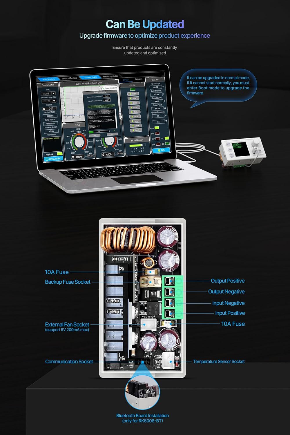
Figure 7.2: PC software interface for monitoring and controlling the power supply via USB connection. Compatible with Windows 7 and above.
Connect the RK6006/RK6006-BT to a computer via the USB communication socket. Install the official PC software (compatible with Windows 7 and above) to monitor and control the power supply remotely. The software allows for advanced data logging and parameter adjustments.
7.6 Mobile APP Communication (Bluetooth - RK6006-BT only)
Figure 7.3: Mobile application interface for controlling the RK6006-BT via Bluetooth. This feature is exclusive to the RK6006-BT model.
For the RK6006-BT model, download the official mobile application (available for Android and iOS) to control the power supply wirelessly via Bluetooth. Ensure Bluetooth is enabled on your mobile device and the RK6006-BT unit. The app provides a convenient interface for setting parameters and monitoring output.
7.7 Firmware Updates
The RK6006/RK6006-BT supports firmware upgrades to optimize performance and add new features. Firmware updates can typically be performed via the PC software. Follow the instructions provided with the firmware update package carefully.
8. Maintenance
8.1 Fuse Replacement
The device is protected by a 10A fuse. If the unit fails to power on or operate correctly, check the fuse. A spare fuse is provided in the backup fuse socket. To replace a blown fuse:
- Disconnect all power from the unit.
- Locate the fuse holder on the rear of the unit.
- Carefully remove the blown fuse.
- Insert a new 10A fuse into the holder. Ensure it is securely seated.
- Reconnect power and test the unit.
8.2 Cleaning
Clean the exterior of the unit with a soft, dry cloth. Do not use abrasive cleaners or solvents. Ensure ventilation openings are free from dust and debris to maintain proper cooling.
9. Troubleshooting
- No Power: Check the input power source and ensure it is supplying voltage within the specified range. Verify that the 10A fuse is intact and not blown.
- Incorrect Output Voltage/Current: Double-check your settings using the V-SET and I-SET buttons. Ensure the input voltage is sufficient for the desired output voltage (considering the buck working mode).
- Communication Issues (PC/Mobile App):
- For USB: Ensure the USB cable is properly connected and the correct drivers are installed on your PC. Verify the PC software is compatible with your operating system (Windows 7+).
- For Bluetooth (RK6006-BT only): Ensure the Bluetooth module is correctly installed, Bluetooth is enabled on both the power supply and your mobile device, and you are within range.
- Over-Temperature Protection (OTP): If the system temperature exceeds 80℃, the unit will activate over-temperature protection. Ensure adequate ventilation around the unit and that the cooling fan is operating correctly when needed. Reduce the load if necessary.
10. Warranty and Support
For warranty information, technical support, or service inquiries, please contact your retailer or the manufacturer directly. Keep your purchase receipt as proof of purchase.